Facebook
 Google
 GitHub
 Linkedin
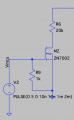
@ScottWang, Thanks! I did find an opamp2 too. I did find a potentiometer from the LT Spice's yahoo group.I was used the normal op amp to replaced it, but I still can't find the potentiometer, it's weird, I used the pot before, but I can't find it after I was updated a couple times later.
The op amp is at the\lib\sym\opamp\opamp.asy
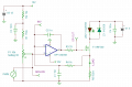
Constant current source for a laser diode
- Thread starter electrophile
- Start date