 Facebook
 Google
 GitHub
 Linkedin
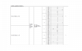
(I attached a photo of the datasheet) I'm having a hard time understanding it, I'm new to this. I have a multiplexer that switches when I give it 7,5V, I want it to switch at 3V.
Currently VDD = 15V, VEE = -15V. Should I change it to +-5V?
Currently VDD = 15V, VEE = -15V. Should I change it to +-5V?
Attachments
-
 70.9 KB Views: 19


