Configuring a XOR gate to oscillate in the kHz range

Papabravo

Joined Feb 24, 2006
22,105
As far as I can tell, it isn't possible to label the power supply output as Vdd or Vcc. In the simulation of your post #4, the power supply output is labeled V1.
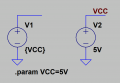
You can label a component anything you want, but your focus is in the wrong place. The name VDD or VCC for the logic libraries should be a netname or a parameter. Like this:
1657644647059.png
 

crutschow

Joined Mar 14, 2008
38,670
As far as I can tell, it isn't possible to label the power supply output as Vdd or Vcc. In the simulation of your post #4, the power supply output is labeled V1.
My simulation in post #4 used a different .lib model (not in those I posted for you) that doesn't require Vdd.

But you are confusing V1, the supply name, with the output net label, which is entirely different and unrelated.

I'm referring to labeling the output Net Name (Label Net under the Edit dropdown or F4) for the output node (below):
So the power supply name here is V1 with an output Net Name of Vdd.

Learn to use net names for all the nodes you want to display, as it makes it much easier to see what signals are being plotted.

1657644771942.png
 

eetech00

Joined Jun 8, 2013
4,723
As far as I can tell, it isn't possible to label the power supply output as Vdd or Vcc. In the simulation of your post #4, the power supply output is labeled V1.
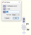
Post #42 reflects the following "attribute" values for an "Independent Voltage Source" device:
"V1" is the "Instance Name"
"VDD" is a wire "Net Label"
"5V" is the "DC Value", "V" is optional

A net label, usually attached to the wire of a voltage source output, must be present on the schematic for the CD4000_v or 74HC_v libraries to work.
Use VDD net label name for the CD4000_v.lib library.
Use VCC net label name for the 74HC_v.lib library.
 

Thread Starter

PeteHL

Joined Dec 17, 2014
585
@crutschow, I believe that there should not be a dot in front of lib in the spice directive. That is for a CD4000 circuit, the directive should be lib CD4000_v.lib. In the simulation that I attempted, the dot at the beginning caused the program to report that it couldn't find the gate.

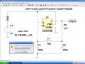
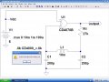
However, even with the changed directive it wouldn't run the simulation. See my attachment here. The program reported that "it can't resolve Vdd1=(Vdd), also Speed1=(Speed) and tripdt1=(tripdt).XOR-OSC.JPG
 

eetech00

Joined Jun 8, 2013
4,723
@crutschow, I believe that there should not be a dot in front of lib in the spice directive. That is for a CD4000 circuit, the directive should be lib CD4000_v.lib. In the simulation that I attempted, the dot at the beginning caused the program to report that it couldn't find the gate.

However, even with the changed directive it wouldn't run the simulation. See my attachment here. The program reported that "it can't resolve Vdd1=(Vdd), also Speed1=(Speed) and tripdt1=(tripdt).View attachment 271342
There should be premade symbols that come with the library. They will have the necessary parameters pre-defined.

Anyway....place these directives on the schematic somewhere. They are missing.

.param VDD=5
.param Speed=1.0
.param tripdt=5e-9

Your VDD net label looks strange. Remove the label and connect the wires together, then attach the net label to the wire.
When creating the label, leave the port type set to "none", so we can see if its attached correctly.
 

crutschow

Joined Mar 14, 2008
38,670
QUOTE="PeteHL, post: 1746977, member: 258803"]
I believe that there should not be a dot in front of lib in the spice directive.
[/QUOTE]
No, there needs to be a dot in front of the lib command (.lib).
I wouldn't have put it there if it weren't needed.

And that CD4070B model is not from the CD4000 library I posted.
Where did you find it?
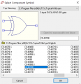
You need to go to the sym\Digital file (below).

1657677048337.png

What are all those directives at the top of the page for?
You don't need those with the CD4000 models.

Below is my simulation of the circuit:
Note the .lib command, and none of the directives that you have, or that eetech00 suggested (don't know why you think you need them(?)).

1657676649666.png
 
Last edited:

eetech00

Joined Jun 8, 2013
4,723
I believe that there should not be a dot in front of lib in the spice directive.
No, there needs to be a dot in front of the lib command (.lib).
I wouldn't have put it there if it weren't needed.
Yes there does need to be a dot in front of the lib directive.
.lib is not a command, it is a spice directive. It should look like this:

.lib CD4000_v.lib

And that CD4070B model is not from the CD4000 library I posted.
Where did you find it?
You need to go to the sym\Digital file (below).
What are all those directives at the top of the page for?
You don't need those with the CD4000 models.
Those are not directives they are parameters. And yes, you do need those parameters with the CD4000 models.
They are already applied to the CD4000 symbol library. But since the TS didn't know about the symbols (and wasn't told), the TS made an effort to make his own and added the parameters. Since he made his own symbol, it needed the parameters I suggested to make it functional.

Below is my simulation of the circuit:
Note the .lib command, and none of the directives that you have, or that eetech00 suggested (don't know why you think you need them(?)).
I've explained why I correctly made the suggestions.
It would have helped if you mentioned use of the CD4000 symbol libraries to the TS.
 
Last edited:

MisterBill2

Joined Jan 23, 2018
27,977
Here we are seeing another advantage of using simulators.
Why not use some other device with an inverter function? A dual input NOR gate or a dual input NAND gate? Or even just a single input NOT function??
Was there a specific benefit claimed for the XOR device???
 

Thread Starter

PeteHL

Joined Dec 17, 2014
585
Here we are seeing another advantage of using simulators.
Why not use some other device with an inverter function? A dual input NOR gate or a dual input NAND gate? Or even just a single input NOT function??
Was there a specific benefit claimed for the XOR device???
The metal detector needs a XOR gate to provide a sum and difference output from the outputs of the two oscillators at input to the gate. The detector is simplified by configuring the other gates of the CD4070 as oscillators.
 

Thread Starter

PeteHL

Joined Dec 17, 2014
585
QUOTE="PeteHL, post: 1746977, member: 258803"]
I believe that there should not be a dot in front of lib in the spice directive.
No, there needs to be a dot in front of the lib command (.lib).
I wouldn't have put it there if it weren't needed.

And that CD4070B model is not from the CD4000 library I posted.
Where did you find it?
You need to go to the sym\Digital file (below).

View attachment 271345

What are all those directives at the top of the page for?
You don't need those with the CD4000 models.

Below is my simulation of the circuit:
Note the .lib command, and none of the directives that you have, or that eetech00 suggested (don't know why you think you need them(?)).

View attachment 271344
[/QUOTE]
QUOTE="PeteHL, post: 1746977, member: 258803"]
I believe that there should not be a dot in front of lib in the spice directive.
No, there needs to be a dot in front of the lib command (.lib).
I wouldn't have put it there if it weren't needed.

And that CD4070B model is not from the CD4000 library I posted.
Where did you find it?
You need to go to the sym\Digital file (below).

View attachment 271345

What are all those directives at the top of the page for?
You don't need those with the CD4000 models.

Below is my simulation of the circuit:
Note the .lib command, and none of the directives that you have, or that eetech00 suggested (don't know why you think you need them(?)).

View attachment 271344
[/QUOTE]
 

Thread Starter

PeteHL

Joined Dec 17, 2014
585
Thanks very much Crutschow! I will try following your advice later today.

The CD4070B model in my post #44 is from the CD4000_v library that you provided. Here is how I generated it.
1.Click on 'open' in the drop-down menu of 'File'.
2.Select 'files of type' = All Files (*.*).
3. Navigate to \lib\CD4000_v.
4. Open the file CD4000_v.
5.Scroll down through the displayed lines of code to the line .SUBCKT CD4070B.
6. Right-click on the line, then left-click on 'create symbol'.
7. Left-click on 'yes' to automatically create.

Pete
 

crutschow

Joined Mar 14, 2008
38,670
Thanks very much Crutschow! I will try following your advice later today.

The CD4070B model in my post #44 is from the CD4000_v library that you provided. Here is how I generated it.
1.Click on 'open' in the drop-down menu of 'File'.
2.Select 'files of type' = All Files (*.*).
3. Navigate to \lib\CD4000_v.
4. Open the file CD4000_v.
5.Scroll down through the displayed lines of code to the line .SUBCKT CD4070B.
6. Right-click on the line, then left-click on 'create symbol'.
7. Left-click on 'yes' to automatically create.
No. You don't open any files.
You are making it way harder than it needs to be.

After you've put the files in the proper location in the LTC library, all you need to do is go to the "View" drop down, select "Component" (or press F2), and select Digital as shown in post #46.
 
Last edited:

Thread Starter

PeteHL

Joined Dec 17, 2014
585
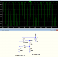
??? from where the 160kHz pops out
View attachment 271397
In the original design of the metal detector, the author of that original design said that the oscillation frequency of the oscillators should be around 159 kHz with a 1 kHz difference frequency. That is where I got 160 kHz from. But I don't think that 160 kHz is etched in stone. In your circuit, capacitance of C1 and C2 is relatively much larger than that of the original design and so you get a lower oscillation frequency. Actually I determined by working with the actual circuit (hardware) that capacitance of the pair of capacitors of the original published design for each of the two oscillators is much too low to cause oscillation in the kHz range.

The original published design of a metal detector is shown in the file MTL-DET-PUB.pdf attached to my post #16 in this thread.
 

Thread Starter

PeteHL

Joined Dec 17, 2014
585
No. You don't open any files.
You are making it way harder than it needs to be.

After you've put the files in the proper location in the LTC library, all you need to do is go to the "View" drop down, select "Component" (or press F2), and select Digital as shown in post #46.
I'll give that a try, thanks.
 
Last edited:

Thread Starter

PeteHL

Joined Dec 17, 2014
585
No. You don't open any files.
You are making it way harder than it needs to be.

After you've put the files in the proper location in the LTC library, all you need to do is go to the "View" drop down, select "Component" (or press F2), and select Digital as shown in post #46.
Sorry, but I don't see 'Component' in the 'View' drop down menu.
 

Thread Starter

PeteHL

Joined Dec 17, 2014
585
My mistake.
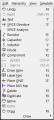
It's in the "Edit" drop down menu (10th item down):
Pressing the F2 key should also bring it up.

View attachment 271460
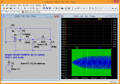
'I think that finally I'm doing everything in the way that you said I should. Sadly, I still could not get the simulation to run. See the below screenshot. As you instructed in your post #35, I unzipped CD4000_v.zip to the lib folder.

SIM0718.JPG
 

crutschow

Joined Mar 14, 2008
38,670
And did you put all the files in the sub directories where I stated?
You can't just dump them all into the lib folder.

Where exactly is the CD4000_v.lib file?
 
Last edited:
Top