Configuring a XOR gate to oscillate in the kHz range

Thread Starter

PeteHL

Joined Dec 17, 2014
583
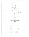
The attached circuit diagram is taken from Rudolph Graf's Encyclopedia of Electronic Circuits. The second gate of the 4070 Quad exclusive OR IC supposedly oscillates at 161 kHz given the component values shown. However, I measured it oscillating at 1.8 mHz, so clearly there is something wrong with the design.

What component values would result in oscillation at about 161 kHz? Inductor L1 must have inductance not much less than 10 mH as I'm showing part of the circuit of a metal detector and the search coil of the detector connected to the first gate of the 4070 must have inductance of around 10 mH to adequately detect.

Also I'd love to read an explanation as to how the arrangement of connection of components to the gate cause it to oscillate and/ or an equation for frequency of oscillation as a function of values of the relevant components.
XOR-OSC.jpg
 

Papabravo

Joined Feb 24, 2006
22,084
You have an L in parallel with a C. The resonant frequency of such a circuit can be approximated by the following expression:

\( f_0\;=\;\cfrac{1}{2\pi\sqrt{LC}}\;=\;(2\pi\sqrt{100e{-12}*10e{-3}})^{-1}\approx159.15\text{ kHz.} \)

There must be something else going on. What that could be I don't know. You are there, but I am not.
 

Thread Starter

PeteHL

Joined Dec 17, 2014
583
In the circuit diagram in post #1, my hack is to make revised C2 = C3 =120 pf where L1 = 10 mH. This results in the gate oscillating at 135 kHz. But I dislike changing the circuit without really understanding what I'm doing.

The design of the circuit is to make the frequency of oscillation of the first gate that the search coil is connected to 1 kHz less than that of the fixed frequency of oscillation of the second gate. So I think that what the actual frequency of oscillation of the second gate is is unimportant.

The third gate mixes the outputs of the first and second gates, and the fourth gate is configured as a low pass filter to cut out the sum while passing the difference of the outputs of the twin oscillators.
 

crutschow

Joined Mar 14, 2008
38,589
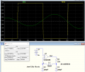
My LTspice simulation also showed a several MHz oscillation.
When I removed C1, then the oscillation went to 158.7KHz, very near the 159.2KHz calculated for the LC tank values used below (10mH in parallel with 100pF series equivalent).

I expect C1 was causing the high-frequency oscillation from it providing a path for positive feedback caused by the high-frequency phase-shift of the gate.
C1 has a low impedance at a couple MHz so the feedback signal is coupled directly through it.
Since C2 and C3 in series through the ground connection now provide the tank parallel capacitance, I don't see a need for C1.

1653361377954.png
 
Last edited:

k1ng 1337

Joined Sep 11, 2020
1,038
My LTspice simulation also showed a several MHz oscillation.
When I removed C1, then the oscillation went to 158.7KHz, very near the 159.2KHz calculated for the LC tank values used below (10mH in parallel with 100pF series equivalent).

I expect C1 was causing the high-frequency oscillation from it providing a path for positive feedback caused by the high-frequency phase-shift of the gate.
C1 has a low impedance at a couple MHz so the feedback signal is coupled directly through it.
Since C2 and C3 in series through the ground connection now provide the tank parallel capacitance, I don't see a need for C1.

View attachment 267899
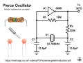
His circuit looks a Piece oscillator with an LC circuit instead of a crystal and resistor. The other difference is a XOR gate with one input is tied high and not an inverter, why is that?

Looking at the XOR truth table, it's equal to an inverter in this situation?

download.png
 
Last edited:

Papabravo

Joined Feb 24, 2006
22,084
His circuit looks a Piece oscillator with an LC circuit instead of a crystal and resistor. The other difference is a XOR gate with one input is tied high and not an inverter, why is that?

Looking at the XOR truth table, it's equal to an inverter in this situation?

View attachment 267906
That's an excellent question. The XOR gate with one input high is an "inverter", but it is also a "buffered" part. When I want to make a circuit like this, I usually use an unbuffered part like 74LVC1GU04, or a 4069UB.
 

Ian0

Joined Aug 7, 2020
13,163
At a guess, it must have been part of a larger project, where there happened to be a spare section of a quad ex-or gate. A nor or nand gate with the spare pin tied high or low would work just as well (or just as badly).
 

crutschow

Joined Mar 14, 2008
38,589
He mentioned mixing two signals to get the difference frequency, which can be done with an XOR gate, which acts as a one-bit multiplier.
The third gate mixes the outputs of the first and second gates, and the fourth gate is configured as a low pass filter to cut out the sum while passing the difference of the outputs of the twin oscillators.
 
Last edited:

Papabravo

Joined Feb 24, 2006
22,084
That may help for higher frequencies, but should not be a factor for a 160kHz oscillator.
It is true that I have not had occasion to make an oscillator at less than about 1 MHz. for quite a while. I think it was for an 8008 that ran at 487.5 kHz., but that was a long time ago.
 

AnalogKid

Joined Aug 1, 2013
12,184
However, I measured it oscillating at 1.8 mHz, so clearly there is something wrong with the design.
No.

Clearly there is something wrong, but I would start with a wiring error or your assembly technique. You forgot the largest variable in the equation - you. Example: Is C1 100 pF, or 10 pF?

Separate from that -

Besides the fact that the circuit in post #1 should oscillate with just about any inverting gate, the post does not say which type of 4070 is being used. Over the years, "standard" CD4xxx CMOS part numbers have had no suffix, A, B, U, and UB. There are large differences among the various flavors in how they perform in what basically is an analog application (the gate or inverter is acting as a medium-gain inverting amplifier) of a digital part. Each has a different forward gain and gain-bandwidth. The first edition of the book was published in 1985, way after B-series CMOS was introduced, so the 4070 probably is a B-series part; but we don't actually know.

Also, there can be large differences among "equivalent" parts from different manufacturers, including things like stray capacitances and inductances in the package and the chip.

ak
 
Last edited:

Thread Starter

PeteHL

Joined Dec 17, 2014
583
@crutschow

Your post #4, thank you, Crutschow!

Don Lancaster in his CMOS COOKBOOK warns against using the 4030, saying that early versions of it had very low input impedance and behaved erratically in pulse circuits. Use the 4070 instead, he wrote.
 

k1ng 1337

Joined Sep 11, 2020
1,038
That's an excellent question. The XOR gate with one input high is an "inverter", but it is also a "buffered" part. When I want to make a circuit like this, I usually use an unbuffered part like 74LVC1GU04, or a 4069UB.
I have tested the pierce circuit I posted with the CD4069 and 74HC14 inverters (unbuffered) with good results with a 32.768kHz crystal for a RTC. I don't see why it wouldn't work with a resonator or LC circuit instead of a crystal resulting in a lower Q factor.

@crutschow

Your post #4, thank you, Crutschow!

Don Lancaster in his CMOS COOKBOOK warns against using the 4030, saying that early versions of it had very low input impedance and behaved erratically in pulse circuits. Use the 4070 instead, he wrote.
To understand the operation of your circuit, check out this link about the basic requirements for oscillation.

For your example, the XOR gate (I think) ideally provides 180 degrees phase shift and the other components must cover the other 180 to achieve oscillation so that as the signal travels through the loop, it 'arrivies' back at the starting point just in time to kick start the next pulse. As crutshow has shown, by reducing the capacitance, the frequency was lowered but did not affect the operation because the basic criteria for oscillation was met. Note the logic gate is the only active device in the circuit and so provides the needed gain.


Pretty cool stuff. Similar behavior exists in almost every repetitive mechanical pattern. Which can lead to bridges falling down!
 
Last edited:

Thread Starter

PeteHL

Joined Dec 17, 2014
583
Attached to my post is the published schematic diagram of a metal detector. We've already discussed configuring U1A and U1B XOR gates as oscillators. What I'd like are comments on the viability of the connection from the output terminal of gate U1C to an input terminal of gate U1D, and the configuration of gate U1D as a low pass filter with a cut-off frequency of 10kHz. Today, June 12, I have deleted the somewhat unclear originally attached diagram and replaced it with a better one.
 

Attachments

Last edited:

AnalogKid

Joined Aug 1, 2013
12,184
The various combinational inputs notwithstanding, early CMOS gates were little more than high gain amplifiers. As such, they could act as a simple inverting audio gain stage within limits. As a proof of concept when I was in school, I once built one channel of a stereo amplifier complete with an equalizing phono preamp stage, full tone controls, and a class D "power" stage, using nothing but 4049 hex inverters.

I never tried this with more complex gates, and an XOR is the most complex kind, with a lot more stuff between the inputs and the output. Still, the idea certainly is valid. And viable.

U1 A, B, and D are configured as simple inverters. A modification would be to use three sections of a CMOS hex inverter for those three sections, and 1/4 of a CD4070 as the mixer (U1C). Also, U1D is configured for a gain of 5, and the circuit will not drive normal headphones. To fix this, change that stage to an LM386, a small audio power amplifier.

ak
 
Last edited:

Ian0

Joined Aug 7, 2020
13,163
The trouble with analogue applications of CMOS gates is that they turn out to be rather less “micro power” than you expect because the standing current increases as the input voltage gets close to halfway between the supplies.
 
Top