 Facebook
 Google
 GitHub
 Linkedin
I am facing the CE failure issue in one of my design.
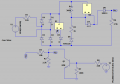
Major components: SCR, MOSFET, Controller.
Project: Timer based product.
Working: Initially the SCR in OFF condition for 1 milli second means controller gives the high signal to the base of NPN when the set timing has been complete from the controller afterwards SCR has been ON and will be on condition(for rest of 9 milli second) until zero crossing detect.
By turning ON/ OFF the SCR resulting to create the unwanted harmonics causing it failing in the CE test.
CE test results attached and schematics attached below.
SCR part number: TS420-600
MOSFET part number: 4NK80ZT4 DPAK
Attachments
-
 22.3 KB Views: 15


