concerning the black plastic spot on the pcb of display modules, in search i found it is an ic/micro-controller/interface under it, but why do manufacturers do this and not leaving it exposed like other components?
chip-on-board is a chip that is wired directly to the motherboard. The chip is usually covered with a coating of epoxy or resin to protect it the way a heatsink does, as well as protecting the chips and wires from damage. This is where the term “glop-top” comes from. It is a cost-effective method of electronic packaging, but the disadvantage is that a chip cannot be replaced without desoldering, the way a socketed chip can. COBs are popular in small circuit boards because they require little physical space the way a heatsink does.
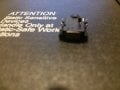
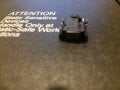
concerning the black plastic spot on the pcb of display modules, in search i found it is an ic/micro-controller/interface under it, but why do manufacturers do this and not leaving it exposed like other components?View attachment 200511
In the manufacturing process of the LCD controller board, the MCU chip is mounted directly on to the PCB.
Then the black epoxy is placed over the chip to protect it (instead of using off-the-shelf chips that are prepackaged in plastic). This is a cost saving to the manufacturer.
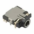
thanks you all, i very appreciate your response .. i have another question but about a different thing, do i have to put it in a new thread? i have got a 3.5mm audio connector, it's smt but has short/flush pins not pads .. how to solder it? it's cui-devices SJ-3506-SMT-TR
the pins are flush with it's bottom side, i wonder how the pcm mount will be .. is it pads? or need an connector/addapter to sit on?
thanks you all, i very appreciate your response .. i have another question but about a different thing, do i have to put it in a new thread? i have got a 3.5mm audio connector, it's smt but has short/flush pins not pads .. how to solder it? it's cui-devices SJ-3506-SMT-TR View attachment 200520
the pins are flush with it's bottom side, i wonder how the pcm mount will be .. is it pads? or need an connector/addapter to sit on?
There most certainly is. Look in the lower left right side:
There you will find the recommended "pad" sizes. For real SMD, they are not that small. But for mounting sewing-needle pins, you will need to add a lot of solder.
It does say how to mount on a PCB but one must be familiar with design I'm not trying to beat you up one chooses every aspect of the components it's a matter of cost it's a matter of real estate the size of your PCB how many layers it will have the complexity the simplicity. The mere fact that if you purchased that component you should be intimately aware of why you purchased it and if not there's no rule saying that you cannot adapt it if you have the skill set. It's why I consider electronics fun I can get away with murder.
There you will find the recommended "pad" sizes. For real SMD, they are not that small. But for mounting sewing-needle pins, you will need to add a lot of solder.
It does say how to mount on a PCB but one must be familiar with design I'm not trying to beat you up one chooses every aspect of the components it's a matter of cost it's a matter of real estate the size of your PCB how many layers it will have the complexity the simplicity. The mere fact that if you purchased that component you should be intimately aware of why you purchased it and if not there's no rule saying that you cannot adapt it if you have the skill set. It's why I consider electronics fun I can get away with murder.
thanks you for your advice, i chosen it over the switchcraft some by fault, i saw the pins i thought it is a through hole and i can use it with a breadboard but when it arrived i realized it is a surface mount .. i didn't got aware much as should be before i buy it
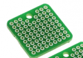
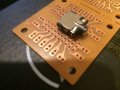
If you have some prototype "stripboard" like this:
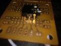
or this:
You just might be able to solder the jack you have to 0.1: 'header pins" to match 0.1" on-center bread board holes. If not, your best bet is to find a jack with a more typical (i.e., 0.1") pin spacing.
You just might be able to solder the jack you have to 0.1: 'header pins" to match 0.1" on-center bread board holes. If not, your best bet is to find a jack with a more typical (i.e., 0.1") pin spacing.
Try it, nothing to lose. By my calculations, there was about 0.5 mm or so misalignment. Then, the holes will allow you to add 0.1" on-center pinheaders to match the breadboard perfectly.
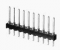
Like this:
Very cheap and can be broken to the right length. If you need to skip a pin, no big deal.

 Facebook
 Google
 GitHub
 Linkedin




 .. i have another question but about a different thing, do i have to put it in a new thread? i have got a 3.5mm audio connector, it's smt but has short/flush pins not pads .. how to solder it? it's cui-devices SJ-3506-SMT-TR