Computing an E field

Thread Starter

davebee

Joined Oct 22, 2008
540
Suppose I wanted to calculate the electric field in an area around a conductor of arbitrary shape, like the globe at the top of a Van de Graaff generator, where the conductor is quite symmetric but is not a sphere; the shape is somewhat flattened and has a large hole in one end.

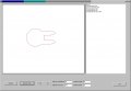
A vertical cross-section of the shape will be symmetrical with any other vertical slice. So suppose we took that slice (like a flattened letter "C") and drew it on a grid in a computer program. Let it initially have charge equally distributed among all cells that are part of the connected "C".

Since we know the exact distribution and location of charge, then at each cell in the grid, we can calculate the magnitude and direction of the E field by summing the contribution from each cell of charge from the amount and location of that charge, as per Coulomb's law.

Then, on the surface of the shape, wherever the E field is not normal to the surface, redistribute charge a slight amount in the direction that the charge would naturally flow due to the E field.

Then recalculate the E field over the entire grid again.

Continue iterating until the E field is normal to the shape and no more charge redistribution is needed.

Then this should model the real-life E field around such a shape.

Is there any problem with this approach?

My goal is to get a better understanding of how the field varies near the opening into the shape, for different sizes and shapes of openings.
 

studiot

Joined Nov 9, 2007
4,998
What you are describing is called the finite element method.

Basically it involves setting up a geometric grid in space and applying known conditions at some points of the grid.

Then by repeatedly apply assumed field equations for E you derive a series of simultaneous equations whose constants can be determined from the known values at the specified points.
Then the conditions over the rest of the grid can then be found.

I say assumed equations because it is usual to assume simpler (often linear) equations to make the calculations easier and quicker. This approach works if the grid mesh is fine enough so the usual method is to calculate models with successively finer grids until there is no difference in the calculated values, between models.
This is thus a method of successive approximations converging (hopefully) to a solution.

It is interesting to note that Stokes theorem provides us with an alternative, known as the boundary element method. this methods needs considerably less work (calculation) because Stokes theorem leads to the conclusion that so long as all points on the boundary are known, they completely define all interior points.
 

Thread Starter

davebee

Joined Oct 22, 2008
540
I've heard of finite element analysis but have never worked with such a system. I'm not sure that I could use any Stokes simplification because basically I'm analyzing a conducting wire which has no interior points. I wouldn't know how to do it, anyway.

The one (physics) consideration I'm not sure of is suppose there is a charge on one side of a conducting object, and I'm summing all the charge contributions to a cell on the other side of the object.

My gut feeling tells me that the field from that charge will be "blocked" from reaching the other side of the conducting object, but Coulomb's law seems to tell me that I must add its field contribution to the cell under calculation as if the conducting object weren't there. Does that sound correct? Do I ignore the presence of the conducting surface as I accumulate all point charge contributions at each cell?

This is just for a home hobby calculation, not for work or a commercial product, so there is no need for it to be particularly detailed or sophisticated or fast, but I would like to get it correct.
 

Thread Starter

davebee

Joined Oct 22, 2008
540
Here's a screenshot of my program as far as I've gotten with it.

Instead of analyzing a circle with an opening, I started working with three intersecting ellipses to try to get a better sense of the field between the two smaller ellipses; what different geometries would result in a low or zero field value in a region.

(But I'd like to also have it able to analyze the sphere-with-an-opening case, too.)

I'm thinking about the design of a static electric generator machine with a collector like a Van de Graaf but instead of having a belt charge carrier, it would have a disk charge carrier like a Wimshurst, so the collector would need a region that a spinning disk could carry charges into, where the inner region has zero or low field for the charge transfer.

So far, the program can take screen parameters for the two smaller ellipses, calculate all three shapes, fill an array with the perimeter values and plot to the screen.

The nodes and array look like this:

type
ChargeNode = record
x: integer;
y: integer;
charge: integer;
math_x: double;
math_y: double;
normal_x: double;
normal_y: double;
efield_x: double;
efield_y: double;
efield_magnitude: double;
end;

chargeshape: array[0..nodes] of ChargeNode;

where the x and y are the screen display pixel coordinates and the rest are the physics values.

I think all I need to do is to populate the math coordinates (the point on the mathematical shape closest to this pixel) and then it should be able to calculate the E field at each node with one traversal of the array for each node. For 845 nodes, this is only like 700K calculations for one full pass, so it should be fairly fast.

After that comes the heavy work - calculating the normal to the surface at each point, then repeatedly doing charge redistribution and E-field recalculation, which hopefully will converge to a final stable charge distribution, then finding the field for every point on the screen, then finding a nice way to display it visually - field lines, or equipotential lines, or color, or something; I don't know, I'm sort of flying by the seat of my pants here; figuring things out as I go.

But if I'm making any major blunders, I'm hoping somebody will be kind enough to point them out.
 

Attachments

Thread Starter

davebee

Joined Oct 22, 2008
540
Thanks for the link.

That site has a link to a program "flexPDE" which looks really nice. FlexPDE lets you define objects in a space, define charges and dielectric properties, then analyze all sorts of things related to the charge and fields throughout that space, with dozens of different ways to plot its results.

It's got a free student version, a free tutorial and plenty of sample shape templates to start from.

If this program is as good as it looks, and can design and analyze the sorts of things I was wondering about, then I'm abandoning my program. I'm still learning how to use it, but it looks like this will do everything I had wanted, and much more.
 
Top