Facebook
 Google
 GitHub
 Linkedin
Hey guys,
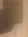
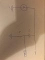
Amazing to be in this group ! Please find attached the diagram of the problem. Please find attached or via the link the wiring scheme.
 [/url][/IMG]
E = 10kV at 60Hz, C1 = 60pF and R1 = 1k.
I have to compute the ac voltage in reference to ground at point [1]. Does it means that I need to compute the voltage at the resistance or the capacitor ? I was thinking it's the the voltage drop between the ground and the resistance, so here is my solution :
Vr(w) = R1/(ZC1(w) + R) * E(w) = 1/(1+jR1C1w)*E(w).
Then I have to compute the cut off frequency, as this is a RC classical scheme,fc = 1(2*π*R*C) right ?
Thanks for the help !
Amazing to be in this group ! Please find attached the diagram of the problem. Please find attached or via the link the wiring scheme.
E = 10kV at 60Hz, C1 = 60pF and R1 = 1k.
I have to compute the ac voltage in reference to ground at point [1]. Does it means that I need to compute the voltage at the resistance or the capacitor ? I was thinking it's the the voltage drop between the ground and the resistance, so here is my solution :
Vr(w) = R1/(ZC1(w) + R) * E(w) = 1/(1+jR1C1w)*E(w).
Then I have to compute the cut off frequency, as this is a RC classical scheme,fc = 1(2*π*R*C) right ?
Thanks for the help !
Attachments
-
 92.2 KB Views: 12
")