Is this device that you want to use to replace the switch still to be operated by a lever or rocker to change it's state or is it to be controlled by an electrical signal ? (Or some other means ?)
Is this device that you want to use to replace the switch still to be operated by a lever or rocker to change it's state or is it to be controlled by an electrical signal ? (Or some other means ?)
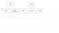
I am using meanwell 0-10V dimming driver to dim the led with the help of Microcontroller and L293D.
Intensity everything working fine but at 0% LED's are turning on at very low intensity which we can only see in a complete darkroom for eliminating that i took a Mosfet for switching but still status remains same then i tried with DPDT relay my problem got solved but while turning on and off in relay sound will come but i want a noise less component. For this i want any component which can replace the same
Driver output & LED Operating voltage - 48V DC
Current -6A
What driver are you using? Does it have an enable pin? If not, why can't you use a solid-state relay to turn it off? Or even a simple transistor switch driven by the arduino when PWM is less than some threshold?
Are you sure that the duty cycle of the pwm output from the Arduino really does go down to zero. Your block diagram does not give us enough information. Post the schematic for both the version using the L293D and the relay. Also the FULL data on the LED driver.
Are you sure that the duty cycle of the pwm output from the Arduino really does go down to zero. Your block diagram does not give us enough information. Post the schematic for both the version using the L293D and the relay. Also the FULL data on the LED driver.
Are you sure that the duty cycle of the pwm output from the Arduino really does go down to zero. Your block diagram does not give us enough information. Post the schematic for both the version using the L293D and the relay. Also the FULL data on the LED driver.
What driver are you using? Does it have an enable pin? If not, why can't you use a solid-state relay to turn it off? Or even a simple transistor switch driven by the arduino when PWM is less than some threshold?
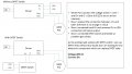
i tried MOSFET switching still the case is same . i took the LED and i connected 100K POT to driver dimming cables and DC i connected to LED then also same by this we can understand that there is no issue in circuit, then i removed DC+ cable and checked the out still it same same i tried by connectng DC+ and removing DC- there is no change in the output. Last i tried DPDT relay then problem got solved. If any electronic component which act as DPDT relay i want to use that in my circuit.
Your description is not clear. When you had NOTHING connected to D+ and D- did the LEDs go out completely ? Where are the DPDT relay contacts connected ? (Dimming input, Driver input, Driver output ?) You are making it hard to solve your problem by not providing the requested information.
Your description is not clear. When you had NOTHING connected to D+ and D- did the LEDs go out completely ? Where are the DPDT relay contacts connected ? (Dimming input, Driver input, Driver output ?) You are making it hard to solve your problem by not providing the requested information.
Those results don't make sense to me. What is going on with the LED's? If you connect only one wire to the string -- either the positive or negative -- they still light up ("same result").
There should be an open circuit if either LED power line is interrupted. Are there other connections to the LED's? (Like a grounded contact and the controller is sending a small amount of AC along with the intended DC.)
Those results don't make sense to me. What is going on with the LED's? If you connect only one wire to the string -- either the positive or negative -- they still light up ("same result"). View attachment 186085
There should be an open circuit if either LED power line is interrupted. Are there other connections to the LED's? (Like a grounded contact and the controller is sending a small amount of AC along with the intended DC.)
If you connect only one wire to the string -- either the positive or negative -- they still light up ("same result"). ---- Yes they are still light up with low intensity
 Facebook
 Google
 GitHub
 Linkedin