 Facebook
 Google
 GitHub
 Linkedin
I was recently looking at some pictures for a linear power supply that went into a process controller I've worked on in the past.
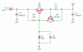
I was able to work out the schematic of the 8V regulator circuit, but the pictures did not include angles that would have allowed me to ascertain the values of three key components, and so I'm asking the brain trust. (Seller wants $250 for it, my curiosity isn't worth that much)
The three components in question are the series pass transistor itself (it is a TO-220 component and gets mounted to the aluminum chassis instead of a heatsink), the zener diode, and a tantalum capacitor paralleling the zener (it would probably be in the neighborhood of 25uF given its appearance).
The 'bulk' power input comes from a frame-mount transformer, fed through a bridge rectifier.
I would believe it would be in the neighborhood of 12VDC; there is also a 5A fuse on that part of the circuit.
The +8V output continues to the backplane inside the process controller, where it is regulated down to 5 volts on each of the circuit boards connected to the backplane.
Attachments
-
 26.1 KB Views: 17


