HI
i would like to have two leds indicating the on /off states of a comparator. eg red for on, green for off.
can it be done, without adding an additional output (transistor) stage?
thank you
dougal
Like crutschow already tried to tell you, good questions bring good answers, and his answer is quite precise for the amount of information that is present in your question.
Unless you are willing to show the circuit where you want to implement this there is nothing more that can be added.
Your question has the words comparator and LED in it. If you combine all possible combinations of available LEDs and comparators, you have well over one million different circuits. That is what is self-evident to us. How do you propose that we narrow down that range of possible circuits to some that meet your actual requirements?
You caused no offense.
It's just that we get so many vague or incomplete questions on these forums where we have to pull the information from the op, piece by piece, to try to determine exactly what he is actually trying to do.
You didn't state what the purpose of this comparator is, or any of its requirements (speed, voltage, accuracy, etc.) or ask how to design one, so I answered the question you asked.
If that answer is sufficient for your purposes, then we are all happy.
hi
apologies to all,
members who might have viewed my previous threads will know that i ramble on a bit,
so on this occassion i thought i would try and be a little more brief and to the point,
looks like i may have overdid it,
a fresh start is needed perhaps,
i have a completed comparator (TS393) stage which has a level detector input comprised of a voltage divider and signal input,
the output is an LED/resistor sourced from the 9v supplyand sinking through the comparators internal transistor,indicating high input,
it is working fine,however i would like to add a second LED to indicate low,
this would be quite easy with an op amp, but i dont really want to abandon the comparator.
and as i would have to modify my existing circuit the simpler the better.
as its some time since i built this circuit, i forgot this was a dual comparator and the second half is spare, so that perhaps could be used for the second led
regards
dougal
HI
i tend to go straight from the back of an envelope to board layout.
this means i dont always have a printable schematic, however spotted this which is pretty close.
'as its some time since i built this circuit, i forgot this was a dual comparator and the second half is spare, so that perhaps could be used for the second led'
so i guess i could just extend the inputs to the second half of the comparator reversing the inv/ non inv connections?
HI
i would like to have two leds indicating the on /off states of a comparator. eg red for on, green for off.
can it be done, without adding an additional output (transistor) stage?
thank you
dougal
Most comparators have an open collector output, so you'll need external circuitry for pull up as well as pull down.
If the application isn't high performance - you can often get away with using an op-amp as a comparator. Most op-amps have something resembling a totem pole output.
'as its some time since i built this circuit, i forgot this was a dual comparator and the second half is spare, so that perhaps could be used for the second led'
so i guess i could just extend the inputs to the second half of the comparator reversing the inv/ non inv connections?
I have done just that, back when I was using a 393 for a line-following robot. Something very similar to this, except the outputs were connected to PNP transistors, which drove the motors as well as the LEDs.
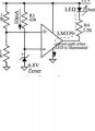
Or, starting with the circuit in post #10, connect the cathode of LED2 to the cathode of LED1. Connect the anode of LED2 to GND through a small signal diode like a 1N914 or 1N4148. When the comparator output is low, LED1 will light. By itself it has a lower Vf than the LED2-plus-diode combination, so LED2 will be off. When the comparator output is off, LED2 will light. Net change to the original circuit plus the 2nd LED: 1 signal diode.
Not quite what I described, but it will work also. In the dl schematic, when the comparator output is low it is sinking two LED's worth of current, although one LED is shunted by the lower Vf diode. In the ak thousand words, only one LED's worth of current is steered between the two LEDs.
Or, starting with the circuit in post #10, connect the cathode of LED2 to the cathode of LED1. Connect the anode of LED2 to GND through a small signal diode like a 1N914 or 1N4148. When the comparator output is low, LED1 will light. By itself it has a lower Vf than the LED2-plus-diode combination, so LED2 will be off. When the comparator output is off, LED2 will light. Net change to the original circuit plus the 2nd LED: 1 signal diode.
I had to draw this out because it didn't make sense. Anode and cathode above are swapped.
YMMV with this circuit. There are some LED currents and color combinations that won't work because the LEDs and diodes will conduct a small amount of current in the proposed configuration. I breadboarded the circuit (and the one I proposed) to prove it to myself and the zero output state would light the one state LED dimly.
I used a 5V supply and 330 ohm resistors, so the LED was operating at about 9mA. I used the same LED color for both indicators.
thanks guys
thats what i was looking for in my original post,as this is part of a prototype project
it could simplify things a little to use a mono comparator.in the final.
however i will be complicating things a little, i will be adding a small piezo buzzer to the red led stage, and using a changeover switch on the inv/noninv inputs.
i will knock up a test board to see which works the best, mono or dual,
particularly whether the leds are lit roughly equally etc.
thanks again
dougal
'as its some time since i built this circuit, i forgot this was a dual comparator and the second half is spare, so that perhaps could be used for the second led'
so i guess i could just extend the inputs to the second half of the comparator reversing the inv/ non inv connections?
 Facebook
 Google
 GitHub
 Linkedin
")