Facebook
 Google
 GitHub
 Linkedin
This is the first time I've ever used an op amp as a comparator and it hasn't gone smoothly!
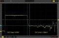
As you see this is powered by 13V. It is meant to be used in a car. It detects when the car engine is turning by the spikes appearing on the 13V line.
The second voltage source simulates the actual voltage measured on the car, which is included.
On my bench, obviously, I just wanted to get the circuit operating in steady state.
I destroyed 3 op amps until I realised that my old Thurlby and Thandar PSU was ringing for a very short duration with a peak at 27V when set to 13V!!!
Please be aware I had this problem with an old T & T before so please check if you are having problems with dead components.
Only it wasn't, surprisingly, what was responsible for their demise. It was only one op amp in the quad pack, configured as a comparator, that was dying.
So I was l flummoxed!!
My only option was to turn the voltage up manually and leaving the output switch on.
That solved that problem, but yet another, number 4 blew.
Again the comparator.
The symptoms? Drawing approx 30mA at 13V (50uA average). The output is at near half rail in steady state.
So I left the damaged device in and did the following.
I applied a sine wave, to simulate the engine voltage spikes, directly to pin 3 then I get a square wave out at pin 7 of the comparator.
The current consumption drops to 15mA and the output toggles between 0V and the half rail steady state voltage.
In steady state this comparator has an approx 500mV input differential voltage. The common mode voltage is, obviously, about 1/2 rail.
In transient, the voltage at pin 6 is approx 12V, which is about 1/2V above the operational common mode voltage.(Vcc-1.5V to 0V)
So in theory you cant drive the input from the output of a neighbouring op amp if the output goes high!!!!
The maximum differential input voltage for this device is +/- 18V. The maximum voltage on any input is Vcc and minimum 0V. The maximum supply voltage is 18V.
So there's no violation of max values.
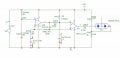
I didn't apply a hysteresis resistor to this circuit due to its nature, but I think I'm going to regret not using a couple of resistors to do so, but this should not kill this circuit? Surely?
I have checked all the protection diodes on every pin and they are ALL intact!!!
There are no components in this circuit that would put any node above Vcc.
The floating node, from the dual Schottky diode, just goes to a charging capacitor that charges between 2.5V and 8.5V and it works fine.
Any ideas??????
As you see this is powered by 13V. It is meant to be used in a car. It detects when the car engine is turning by the spikes appearing on the 13V line.
The second voltage source simulates the actual voltage measured on the car, which is included.
On my bench, obviously, I just wanted to get the circuit operating in steady state.
I destroyed 3 op amps until I realised that my old Thurlby and Thandar PSU was ringing for a very short duration with a peak at 27V when set to 13V!!!
Please be aware I had this problem with an old T & T before so please check if you are having problems with dead components.
Only it wasn't, surprisingly, what was responsible for their demise. It was only one op amp in the quad pack, configured as a comparator, that was dying.
So I was l flummoxed!!
My only option was to turn the voltage up manually and leaving the output switch on.
That solved that problem, but yet another, number 4 blew.
Again the comparator.
The symptoms? Drawing approx 30mA at 13V (50uA average). The output is at near half rail in steady state.
So I left the damaged device in and did the following.
I applied a sine wave, to simulate the engine voltage spikes, directly to pin 3 then I get a square wave out at pin 7 of the comparator.
The current consumption drops to 15mA and the output toggles between 0V and the half rail steady state voltage.
In steady state this comparator has an approx 500mV input differential voltage. The common mode voltage is, obviously, about 1/2 rail.
In transient, the voltage at pin 6 is approx 12V, which is about 1/2V above the operational common mode voltage.(Vcc-1.5V to 0V)
So in theory you cant drive the input from the output of a neighbouring op amp if the output goes high!!!!
The maximum differential input voltage for this device is +/- 18V. The maximum voltage on any input is Vcc and minimum 0V. The maximum supply voltage is 18V.
So there's no violation of max values.
I didn't apply a hysteresis resistor to this circuit due to its nature, but I think I'm going to regret not using a couple of resistors to do so, but this should not kill this circuit? Surely?
I have checked all the protection diodes on every pin and they are ALL intact!!!
There are no components in this circuit that would put any node above Vcc.
The floating node, from the dual Schottky diode, just goes to a charging capacitor that charges between 2.5V and 8.5V and it works fine.
Any ideas??????
Attachments
-
 51.8 KB Views: 65