 Facebook
 Google
 GitHub
 Linkedin
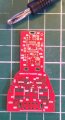
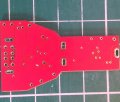
It's nearly all 0402.In other words you are human. I am not sure what else to check at this point. So this is a schematic that has been converted to a PCB or just a protoboard?
Shamefully, considering I was the go to EMC circuit design guy, I left the bandwidth limiting/ suppression caps out and decided to stack them as there is very little space and there has to be a clearance around the board.
This sits in one of those car cigarette lighter usb charger cases. It's ground flooded, with Vcc running along a thick track the other side, which is also ground flooded.
Attachments
-
 578.8 KB Views: 7
 -
 379.9 KB Views: 6
")


