Comparator CD4063B

Thread Starter

dledge

Joined Feb 11, 2014
60
Here is the schematic with the whole thing.
I set it up for a LDR that I had. 39K in the light and 1 meg in the dark. Yours may be different and we would need to change some things.
If you can measure the voltage on the + & - inputs in light and dark and the output we can probably figure it out.
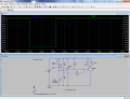
So i figured out the issue with the 'millivolts'. I forgot the pull up resistor on the comparator output. Circuit seems to be working well. I do need to adjust the sensitivity of the POT and the photoresistor. I'm thinking I just need to put additional resistors in series with these two so that their effect is less impactfull within the voltage divider. Am I correct in this train of thought?
 

ronv

Joined Nov 12, 2008
3,770
Could you upload your *.asc file, thanks.
Sure. Here you go.

Ahh, I see you don't want to lock the little guys out when the power fails?

Yes, you can zero in on the trip point. Maybe two pots a large value to compensate for the LDR and a smaller one to fine tune it.
 

Attachments

Thread Starter

dledge

Joined Feb 11, 2014
60
I think this works
Looks like you modified the transistor to be an PNP...

I was actually thinking that when the output of the circuit goes low, the relay would drop to a relaxed state which in turn would drive the signal to the main processor to zero (door closes). When circuit goes high, the relay goes to the activated state and drives the signal to the main processor to 12v (door opens).

I've had a lot of fun playing with this circuit. Utilizing your initial circuit design, I've come up with the attached (which works), but I now would like to fine tune it.
One thing I could not deduce, was the purpose of R3 in your circuit. I started out using this, but then was able to tweak a few other sections and remove this resistor. This tells me I've no clue as to what impact that resistor has...I'm feeling an educational moment coming on...

One of the things I've found, is that the photoresistor is not linear, OR the falloff of the lux is exponential. Either way, the voltage drop on V_in is not linear with a visually consistent drop in light level. I've been trying to figure out ways to compensate for that, but have not had much success.

I've also been trying to tweak the 'sensitivity' or impact that the photoresistor has within the voltage divider. I've found that putting it in series with another resistor has helped.

What I'm really trying to understand now, is which sets of resistors impact the spread of the threshold, as well as how I would bias the the threshold towards either the upper or lower limits. Please see the attached diagram.

My thought, is that if I can bias the V_ref towards the lower threshold boundary, then I will be very close to the circuit I need, AND it should mitigate the non-linear voltage drop of the photoresistor.

I'm guessing I need to:
1. Determine the Threshold
2. Determine the V_ref
3. Set the bias of V_ref to the threshold
 

Attachments

ronv

Joined Nov 12, 2008
3,770
I moved the LDR to the opposite side so the relay will be on when it is dark. I think this closes the door???? Then the relay turns off when it is light and opens the door??? This means when the power fails the door should be open - assuming gravity opens it??? Using post #23, R1 determines how far apart the turn on and turn off values are and the adjustment pot moves the center point up and down. So with those two you should be able to do what you want - I think. :D maybe. :)
To be on the same page lets just talk about the relay being energized or not.
 

Thread Starter

dledge

Joined Feb 11, 2014
60
The LM339 is an OC(open collector), so you need to adding a resistor to pull high.
Ah....but why would the circuit work without that pullup resistor?

Also, I tried the circuit without the use of the relay switch (rely on the transistor) and I'm having great success with this. I also moved the POT to not be in line with the photo resistor. I've not yet determined what impact this has on the threshold...

Would you see any issues with this (See attached diagram).
 

Attachments

Thread Starter

dledge

Joined Feb 11, 2014
60
I moved the LDR to the opposite side so the relay will be on when it is dark. I think this closes the door???? Then the relay turns off when it is light and opens the door??? This means when the power fails the door should be open - assuming gravity opens it??? Using post #23, R1 determines how far apart the turn on and turn off values are and the adjustment pot moves the center point up and down. So with those two you should be able to do what you want - I think. :D maybe. :)
To be on the same page lets just talk about the relay being energized or not.
I can see where I confused you. My apologies.

This light sensor is one of three different external sensors that feeds into a logic circuit. If all three external sensors register 'high', then the door will open. If any one external sensor registers false, the door will close.

I think I errantly included the relay, as it seemed a simple way to force the Vout to be rail to rail (0 or 12v). I discovered I can do the same thing with just the transistor (assuming there is a beefy resistor involved).

So for this light sensing circuit, I just need to make sure that the circuit only goes low (dark) when it is really dark, and that the circuit stays low, unless it really begins to get light again. I'll play with the resistors to see how to adjust the threshold. I'm still not clear on what combination would bias the V_ref towards one threshold or the other. Ideally, I'd like V_ref biased towards the lower threshold.

Regarding the pull up resistor on the open collector...what happens if I leave that off?
 

ScottWang

Joined Aug 23, 2012
7,501
Ah....but why would the circuit work without that pullup resistor?

Also, I tried the circuit without the use of the relay switch (rely on the transistor) and I'm having great success with this. I also moved the POT to not be in line with the photo resistor. I've not yet determined what impact this has on the threshold...

Would you see any issues with this (See attached diagram).
The base current from R3, R4 and R2, if R3 and R4 too big then the bjt can't get the enough base current, it will get into a unstable status, the base current should be has 1/10 c of bjt, and R17 is too big became useless.
 

ronv

Joined Nov 12, 2008
3,770
It's hard to say without the values for R3 & R4, but I would predict that you will have trouble getting enough difference between turn on and turn off (spread) because the transistor will keep the output from going very high. The other problem is the spread between on and off will vary with where you have the pot set.
Right now it is being pulled up thru R3 and R4.
 

ronv

Joined Nov 12, 2008
3,770
OK. I got it..... I think.

The output goes low when it is dark. Same deal. Vary R1 to vary the spread (Smaller makes the spread wider) and adjust the pot to move it up and down the curve. We may still need to make some measurements to understand your sensor. Or do you have a link to it's spec sheet.
 

Attachments

Thread Starter

dledge

Joined Feb 11, 2014
60
OK. I got it..... I think.

The output goes low when it is dark. Same deal. Vary R1 to vary the spread (Smaller makes the spread wider) and adjust the pot to move it up and down the curve. We may still need to make some measurements to understand your sensor. Or do you have a link to it's spec sheet.
Just a quick note that I built the circuit...and it works FANTASTIC. Thank you ronv for all your help.
 
Top