Facebook
 Google
 GitHub
 Linkedin
Need some help understanding this chip.
I've used LM339 comparators before with no issue; however, I'm creating a 12V circuit now and will be using a CD4063B chip.
The circuit will be a light detector. When the surrounding ambient light reaches a certain level, the output needs to go to Logic High. I will need some hysteresis to eliminate bouncing.
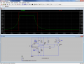
I've built the circuit using the LM339, but when I am trying to map this over to the CD4063B chip, I cannot figure out out to get the hysteresis implemented. Basic schema is attached.
Any help would be appreciated.
I've used LM339 comparators before with no issue; however, I'm creating a 12V circuit now and will be using a CD4063B chip.
The circuit will be a light detector. When the surrounding ambient light reaches a certain level, the output needs to go to Logic High. I will need some hysteresis to eliminate bouncing.
I've built the circuit using the LM339, but when I am trying to map this over to the CD4063B chip, I cannot figure out out to get the hysteresis implemented. Basic schema is attached.
Any help would be appreciated.
Attachments
-
11.1 KB Views: 49