
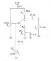
My goal is to determine the DC Load Line.
This is the last problem in the workbook and I haven't encountered any problem that has feedback potentiometer. How do I find the input current and the output current?
This is the last problem in the workbook and I haven't encountered any problem that has feedback potentiometer. How do I find the input current and the output current?
Attachments
-
 578 KB Views: 21
Last edited by a moderator:


