Facebook
 Google
 GitHub
 Linkedin
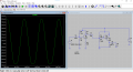
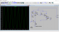
Design a circuit to drive an 8Ω, 0.25W speaker from the output of a function
generator and show the simulation to your instructor. Here are the design specs:
• You may not use more than one supply voltage, i.e., you should design a single supply circuit. If your circuit
needs more than one voltage, e.g., for biasing, you should generate it using resistor dividers, zener voltage
sources, and the like.
• Supply voltage shall be 3V. This is the voltage of 2 AA batteries in series.
• The test input is a 300mV peak-to-peak, 1kHz zero-offset sine-wave.
• Multiple stages are allowed. Example stages include CE amp and emitter follower.
• To get full points for this exercise, you’ll need to implement a small-signal voltage gain of about 7 and have no
noticeable distortion on the speaker waveform.
• Only BJTs, diodes, and passive components are allowed.
I'm trying to get a 7 Small signal voltage but can only reach 4, how can I make it 7?
Thanks a lot for you responses!!
Attachments
-
2 KB Views: 3
Last edited: