Common base BJT amplifier

to be honest, i cannot quite figure out where my calculations have gone wrong. but a gain of 8 sounds more correct.
Ron H in post #16 explained it.

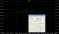
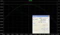
When the frequency is equal to the resonance frequency of the L/C circuit, the L/C combination may be replaced by a short. You can then see that the 1.2k resistor is simply an additional load from the input to ground. Since the source is assumed to be a zero output impedance device, the 1.2k load does nothing when it's connected directly to the source, as it is when the L/C circuit is at resonance.

Off resonance, the impedance of the L/C circuit combined with the 1.2k forms a voltage divider.

So, at resonance, the 1.2k does nothing. Off resonance, it has an effect.
 

steveb

Joined Jul 3, 2008
2,436
to be honest, i cannot quite figure out where my calculations have gone wrong. but a gain of 8 sounds more correct.
I believe your mistake is where you say Ie=Vs/Rin. This would only be true if the 1.2K resistor was not there. You should instead say that Ie=Vs/Rin-I3 where I3 is the current in the 1.2K resistor. Then you need further relations for I3, such as I3=V3/1.2K where V3 is the voltage across the 1.2K resistor. Then you continue until all unknowns are related to know parameters and end up with an equation for Vout/Vin.

The SFG I posted basically does this, although I made a sign mistake.

The previous posts are basically saying the same thing in a different way.

Another way to say it is your gain is Rc/Rin, which includes the 1.2 K resistor, even at resonance. If you look at my gain formula at resonance, it works out to Rc/Re3 which does not depend on the 1.2K resistor.
 
Last edited:

Ratch

Joined Mar 20, 2007
1,070
To the Ineffable All,

I maintain that the 1K2 resistor will not affect the resonant frequency and will reduce the output of all frequencies by the current division rule 1200/(1200+100+26) = 90% . It is simply a shunt that diverts current from the transistor. So we have for a transfer function Vo/Vi = 0.9*1000/(100+26+Ls+1/Cs) = 900Cs/(LCs^2 + 126Cs +1) . Notice at resonance we can substitute w^2 = 1/LC into the transfer function and it reduces to 900/126 = 7.14 . The Bode plots are shown below.

Ratch
 

Attachments

steveb

Joined Jul 3, 2008
2,436
To the Ineffable All,

I maintain that the 1K2 resistor will not affect the resonant frequency and will reduce the output of all frequencies by the current division rule 1200/(1200+100+26) = 90% . It is simply a shunt that diverts current from the transistor. So we have for a transfer function Vo/Vi = 0.9*1000/(100+26+Ls+1/Cs) = 900Cs/(LCs^2 + 126Cs +1) . Notice at resonance we can substitute w^2 = 1/LC into the transfer function and it reduces to 900/126 = 7.14 . The Bode plots are shown below.

Ratch
No, the gain of 7.14 is certainly incorrect, provided that Rc=1K and Re3 = 125 ohms. If you look at the transfer function I derived, and correct for my mistake with the negative sign.

The gain is Av=Rc/Re3 at resonance. At the resonant frequency Wo=1/sqrt(LC):

s^2 = (jWo)^2 = -Wo^2 = -1/(LC)

Hence, the denominator of the transfer function is very simple at resonance.

I do agree with your comment that the 1.2K resistor does not affect the resonant frequency.
 

Ron H

Joined Apr 14, 2005
7,063
To the Ineffable All,

I maintain that the 1K2 resistor will not affect the resonant frequency and will reduce the output of all frequencies by the current division rule 1200/(1200+100+26) = 90% . It is simply a shunt that diverts current from the transistor. So we have for a transfer function Vo/Vi = 0.9*1000/(100+26+Ls+1/Cs) = 900Cs/(LCs^2 + 126Cs +1) . Notice at resonance we can substitute w^2 = 1/LC into the transfer function and it reduces to 900/126 = 7.14 . The Bode plots are shown below.

Ratch
I simulated the actual circuit in LTspice, and the gain at resonance was 7.946, which validates the opinion that I and others have stated, namely that the 1.2k resistor has no effect on the voltage gain at resonance.
Ratch, If you wanted to plot current gain from the voltage source, the indeed approximately 10% of the signal current flows through the 1.2k resistor at all frequencies, but the current gain would be 0.9.
 

Attachments

Ratch

Joined Mar 20, 2007
1,070
steveb,

No, the gain of 7.14 is certainly incorrect, provided that Rc=1K and Re3 = 125 ohms. If you look at the transfer function I derived, and correct for my mistake with the negative sign.

The gain is Av=Rc/Re3 at resonance. At the resonant frequency Wo=1/sqrt(LC):
Did you correct for the shunting effect of the 1K2 resistor? My last posting shows why it drains 10% of the current going into the transistor. So, at resonance, 0.9*1000/126 = 0.9*7.94 = 7.14 . Are we arguing about whether the 1K2 resistor has any effect on the gain? It surely does because it subtracts from the gain current.

By the way, I have a hard time following the analysis you posted. I think your result is too complicated, because you got off course somewhere. Perhaps it would be simpler for you to critique my simpler result to see where I went wrong.

Ratch
 

Ratch

Joined Mar 20, 2007
1,070
Ron H,

I simulated the actual circuit in LTspice, and the gain at resonance was 7.946, which validates the opinion that I and others have stated, namely that the 1.2k resistor has no effect on the voltage gain at resonance.
Ratch, If you wanted to plot current gain from the voltage source, the indeed approximately 10% of the signal current flows through the 1.2k resistor at all frequencies, but the current gain would be 0.9.
I would check your simulation again. How can you explain why it has no effect on gain at resonance? What if the shunt resistor was 126 ohms instead. That would mean that 50% of the current does not flow through the transistor. I still cannot why the gain does not drop to 90% of what it would be if no resistor were present.

Ratch
 

Ron H

Joined Apr 14, 2005
7,063
Ron H,


I would check your simulation again. How can you explain why it has no effect on gain at resonance? What if the shunt resistor was 126 ohms instead. That would mean that 50% of the current does not flow through the transistor. I still cannot why the gain does not drop to 90% of what it would be if no resistor were present.

Ratch
Wasted current through R1 has no effect on the voltage gain at resonance. The LC impedance at resonance is ZERO - ZIP - NADA. The voltage source resistance is zero at all frequencies. Think of the LC circuit as a piece of wire. It doesn't matter how low the shunt resistor is. At resonance, the voltage at the junction of R1, R3, and C1 is identical to the voltage of the source.
 

steveb

Joined Jul 3, 2008
2,436
steveb,

Did you correct for the shunting effect of the 1K2 resistor? My last posting shows why it drains 10% of the current going into the transistor. So, at resonance, 0.9*1000/126 = 0.9*7.94 = 7.14 . Are we arguing about whether the 1K2 resistor has any effect on the gain? It surely does because it subtracts from the gain current.

By the way, I have a hard time following the analysis you posted. I think your result is too complicated, because you got off course somewhere. Perhaps it would be simpler for you to critique my simpler result to see where I went wrong.

Ratch
Yes, the full effects of the 1.2K resistor are included in my analysis. My analysis is probably hard to follow because I use a SFG approach and Mason's gain formula. Most people are not familiar with this, so I understand. However, the formulae are very simple and all effects are included. If you like, I can write out the individual formula used to make the SFG, but it includes all voltage loading effects.

I think the error in your thinking is that the current gain is not the same as the voltage gain. At resonance, the input voltage directly drives the 1.2K resistor with no effective source impedance. Hence, the diverted current has no effect on the voltage gain.

I've checked my work a couple of times now, and it correlates with a spice simulation very accurately.
 
Last edited:

Ratch

Joined Mar 20, 2007
1,070
steveb and Ron H,

Yes, I see what you are talking about now. I should have included R1 in my transfer analysis. I know about signal flow graphs, but I am very rusty, and never have used them much. Thanks to both of you for the correction.

Ratch
 

steveb

Joined Jul 3, 2008
2,436
No Problem Ratch. It's very easy to make mistakes in these problems. I'm not sure, but we may have lost the person who posted the question. Hopefully he sees the that using discussions, thinking, theory and simulation tools, together, eventually leads to the answer.
 

Ratch

Joined Mar 20, 2007
1,070
steveb,

... It's very easy to make mistakes in these problems. ...
Yes, I see my mistake now. I did not take into consideration how much the 1K2 resistor increases the current from the input voltage. 126||1200 = 114 ohms instead of 126 ohms. 1000/114 = a gain 8.77 . Multiplying by the shunt factor of 1200/(1200+126) = 0.9049774 for a gain of 8.77*0.9047774 = 7.94 which is the same as 1000/126 .

Ratch
 

steveb

Joined Jul 3, 2008
2,436
How do I obtain the small signal transfer function to draw bode plots?
anybody?
I thought I would add some information about second order bandpass systems such as this. The second order bandpass system is so common that you should learn the standard form of the transfer function. I've attached a PDF which shows the basic form of the transfer function and makes it easy to identify gain, center frequency and bandwidth.

Whenever you see that you have a second order system with "s" in the numerator and a quadratic of "s" in the denominator, try to put it in the standard form. If you can, then you know it's a bandpass and you can pick out formula for gain, center frequency and bandwidth which allows you to design the circuit by tuning parameters in an intelligent way, rather than just randomly changing numbers in a simulator such as spice.

Using the formula shown, you would end up with the following for your particular circuit.

Gain: Ao=7.94
Center Frequency: fo=10.07 kHz
Half Power Bandwidth: B=1.31 kHz
 

Attachments

Last edited:

hgmjr

Joined Jan 28, 2005
9,027
Steveb inspired me to take a stab at my own solution to this problem.

I believe that the factor \(\alpha\) needs to be included in the final AC gain expression as I have shown in my solution.

hgmjr

PS. I have made the changes to the original write-up per the suggestions by electrician in subsequent replies to this thread. The updated version can be found in this reply further along in this thread.
 
Last edited:

Ratch

Joined Mar 20, 2007
1,070
hgmjr,

Steveb inspired me to take a stab at my own solution to this problem.
You certainly did a very complete and exhaustive analysis.

I believe that the factor needs to be included in the final AC gain expression as I have shown in my solution.
To be complete, yes. But assuming that the current value of the emitter is the same as the collected does not change the response all that much. Your final figure for the gain at resonance is 7.92 vs 7.94 shows that the gain is slightly less due to the loss of current to the base circuit.

Ratch
 

steveb

Joined Jul 3, 2008
2,436
I believe that the factor \(\alpha\) needs to be included in the final AC gain expression

hgmjr
Yes, you are absolutely correct. I started my analysis with the alpha included, and for some reason lost it in the following steps. It was probably just an old subconscious habit to approximate alpha=1, but it's better to keep alpha in the equations.

Good work, by the way!
 
Steveb inspired me to take a stab at my own solution to this problem.

I believe that the factor \(\alpha\) needs to be included in the final AC gain expression as I have shown in my solution.

hgmjr
You certainly get A++ for quality of presentation!

Now, in order to be even more complete, as a SPICE analysis would probably be, you need to take into account at least 4 low-frequency two-port parameters. The values I get from the data sheet are (for an emitter current of 1mA):

hie = 3800 ohms
hre = .00013
hfe = 110
hoe = .0000085 mho (as they used to call them)

Converting to common base parameters, we have:

hib = 34.2287 ohms
hrb = .000160965
hfb = -.9909936
hob = .000000076564 mho
 
Steveb inspired me to take a stab at my own solution to this problem.

I believe that the factor \(\alpha\) needs to be included in the final AC gain expression as I have shown in my solution.

hgmjr
On page 5 of 6, at the top of the page, you say, "The term aR1 is the product of a (I'm using a for alpha) and the collector resistance." Looking at your schematic, it appears that R2 is the collector resistor, so you should replace R1 by R2 in the sentence quoted and propagate that change through the rest of your equations.

I call R2 the collector resistor, and not the collector resistance, because normally the term "collector resistance" refers to an intrinsic property of the transistor, namely, the reciprocal of the hob parameter, the output admittance.

At Eq. 2.2, you say:

gm =IE/Vi

"...it is possible to interpret equation 2.1 as the transconductance of the CB amplifier in Figure 1."

The expression you have given (Eq. 2.1) is the transconductance from the input where Vi is applied, to the emitter of the transistor. The signal has not passed through the transistor at this point, and this expression would not normally be considered the transconductance of the complete amplifier.

The transconductance of the amplifier should be expressed like this:

gm=Ic/Vi

so if you multiply your Eq. 2.1 by alpha, that would be the transconductance of the CB amplifier.

Then your Eq. 2.6 becomes:

Vo
--- = gm R2
Vi

a familiar expression one remembers from vacuum tube days.

These were the two problems I noticed with a quick read through, otherwise it think it's right on.
 
Last edited:

steveb

Joined Jul 3, 2008
2,436
Now, in order to be even more complete, as a SPICE analysis would probably be, you need to take into account at least 4 low-frequency two-port parameters. The values I get from the data sheet are (for an emitter current of 1mA):

Converting to common base parameters, we have:

hib = 34.2287 ohms
hrb = .000160965
hfb = -.9909936
hob = .000000076564 mho
You are correct of course, and a good designer needs all of this in the general case. Still, the question becomes how precise does the model have to be to understand this circuit and predict it's performance.

His analysis includes alpha=hfb and hib. It is clear that hib is critical and is highly dependent on temperature. Including alpha represents a 0.1 % correction to the answer. Now including hob would be less than a 0.01% correction.

We could also say that the frequency limitations of the transistor should be considered. However, CB has very good frequency response and the speed limitations of the transistor would have small effect at 10kHz.

Compare these effect to the uncertainty in transistor parameters, temperature dependence of hib and resistor tolerance (1%), and you can make estimations of what is important. There is always a fine line in modeling as far as what to include and exclude.
 
Top