Common base BJT amplifier

Thread Starter

anik321

Joined Oct 25, 2008
22
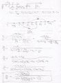
Hey guys. I am trying to understand this common base circuit.

This is what I understand:

1. It is a common base circuit
2. There is a resonant circuit with a small signal source at the emitter.
3. qualitatively I know that at resonance, the impedance will be the lowest, therefore Vout (collector voltage) will be the lowest at this resonant frequency. (lower impedecence->more current through collector/emitter->more voltage drop across Rc.


I just do not understand how to go about starting this analysis. Can you guys help? How can I numerically calculate the resonant frequency?

Here is the circuit:


Thread Starter

anik321

Joined Oct 25, 2008
22
Thank you,

So I have calculated the resonant frequency at which the impedance of the cap and the inductor cancels each other. This works out to be 10khz. (10068khz to be exact)

Here is my DC analysis. (I left out V1, and shorted V2 and V3 to ground)

2V - 0.7 - (Ie*100) - (Ie*1.2k) = 0
Ie ~ 1mA
Vcollector = 10- 1mA(1k) = 9V.


How do I obtain the small signal transfer function to draw bode plots? I prefer using the T model, but i am not sure how to include the inductor.

anybody?
 

hgmjr

Joined Jan 28, 2005
9,027
Thank you,

So I have calculated the resonant frequency at which the impedance of the cap and the inductor cancels each other. This works out to be 10khz. (10068khz to be exact)
That is the frequency I calculated also.

Here is my DC analysis. (I left out V1, and shorted V2 and V3 to ground)

2V - 0.7 - (Ie*100) - (Ie*1.2k) = 0
Ie ~ 1mA
Vcollector = 10- 1mA(1k) = 9V.
Your calculations appear to be correct to me.

hgmjr
 

Audioguru

Joined Dec 20, 2007
11,248
The series LC is a short at resonance.
The AC voltage gain of the transistor is Rc/(RE + Re). Rc is 1k. RE is 100 ohms. Re is the internal Re of the transistor which is about 26 ohms at 1mA. Therefore the voltage gain is 1000/(100 + 26)= 7.94 times.
 

Thread Starter

anik321

Joined Oct 25, 2008
22
The series LC is a short at resonance.
The AC voltage gain of the transistor is Rc/(RE + Re). Rc is 1k. RE is 100 ohms. Re is the internal Re of the transistor which is about 26 ohms at 1mA. Therefore the voltage gain is 1000/(100 + 26)= 7.94 times.
Thank you guys.

Audioguru,

Your calculations even at resonance do not take into account the 1.2k resistor all the way at the bottom.

Are you saying at resonance (when the L and C does not offer any impedance, all the emitter current flows to ground through my ideal signal source and nothing through the 1.2k? Is it safe to assume this for signal sources?

what happens when you are NOT at resonance? how can I sketch a bode plot of this?
 

Thread Starter

anik321

Joined Oct 25, 2008
22
also, my collector voltage at resonance do come extremely close to your gain of 7.94. It is in fact 7.84. (spice)

I am simply trying to understand what happens to the 1.2k and why is it not taken as part of the emitter resistance when calculating Rc/(RE+re)

I the cap and L i am guessing would also give just a 20db*2=40db/dec roll off.
 

steveb

Joined Jul 3, 2008
2,436
I just do not understand how to go about starting this analysis. Can you guys help? How can I numerically calculate the resonant frequency?

How do I obtain the small signal transfer function to draw bode plots? I prefer using the T model, but i am not sure how to include the inductor.

anybody?
It sounds like you understand how to use an equivalent circuit model and you just want to know how to include the inductor. Since you are assuming a small signal AC analysis, you can use the Laplace Transform approach. Replace all inductors with impedance sL and all capacitors with impedance 1/sC. Then, use your normal circuit analysis to find the transfer function output/input. Your transfer function then depends on the complex frequency "s". To get the numerical answer, Matlab is the best choice. You can directly enter the transfer function and get the bode plot. Without Matlab, the math is tedious, but can still be worked out.

This is the basic approach, but if you need more detail, just let us know what part needs clarification or more detail.
 

Thread Starter

anik321

Joined Oct 25, 2008
22
I am OK at best with small signal models.

but the math when you replace inductors with sL and caps with 1/sC gets very tedious. To the point where I cannot envision when the gain is real or not etc.

Is it reasonable to not be able to 'sketch by hand' a bode plot of a transfer function this complicated?

When I look at the circuit, spice simulations give me exactly when I picture in my head. and infact I can easily do it without deriving a transfer function. (i will post a Vmag vs. frequency graph soon)

so yes: my problem is simply deriving the full small signal transfer function.
 

steveb

Joined Jul 3, 2008
2,436
I am OK at best with small signal models.

but the math when you replace inductors with sL and caps with 1/sC gets very tedious. To the point where I cannot envision when the gain is real or not etc.

Is it reasonable to not be able to 'sketch by hand' a bode plot of a transfer function this complicated?
Yes, you are right, the math is tedious. That's why I recommend using Matlab. Matlab lets you just enter the transfer function and then do the bode plot. It is best to get the transfer function is a form of a ratio of two polynomials, and then use the tf command.

If you don't have Matlab, then it is possible to get a bode plot by hand, if you can work out the poles and zeros and use the bode plot graph procedures. Since I haven't actually worked out your problem, I don't know how difficult this would be in your case. Sometimes it's easy, sometimes not. The order of the system does not look too large, and usually a second or third order system can be worked out. But, yeah, it's a pain. It's good to work through a few of these by hand as a student. Then, once you know you can do it, avoid it like the plague and use Matlab. :D
 

steveb

Joined Jul 3, 2008
2,436
I think there is a mistake in your work. I derived the gain relation and calculated the gain at the resonant frequency, but I got a gain of 8. One of your relations looks incorrect. You say that Vin/Rin=ie, but this is the input current.

As far as the phase, you must calculate the complex value of A=Vo/Vi and then take the magnitude as sqrt(Im(A)^2+Re(A)^2 and the phase as atan(Im(A)/Re(A)). Note that Im(A) is the imaginary part and Re(A) is the real part.

When you are at the resonance frequency, the gain is purely real, so A is the magnitude of the gain and the phase is zero.
 
Last edited:

Thread Starter

anik321

Joined Oct 25, 2008
22
steveb,

I also get 8 only when I do not take the 1.2k resistor to be in parallel with the (100+re). Then my Rin is simply:

Rin= jwL+ 1/jwC + 126 (just 126 at resonance)

H(jw)=Rc/Rin = 1k/126 ~8

if you take the 1.2k to be in parallel with the 100ohms then 1.2k//100=113

Rin= jwL+ 1/jwC + 113 (just 113 at resonance)

H(jw)=Rc/Rin = 1k/113 ~8.84
 

steveb

Joined Jul 3, 2008
2,436
You seem to be making an honest effort to learn this, so I thought I would post my work, since it could help you. Please double check my work. I make just as many mistakes as the next guy, and I'm a little rusty on this stuff.

I was taught to use signal flow graphs (SFG) and Mason's gain formula, and I don't expect they teach that anymore, but you should be able to understand the mathematical relations in the SFG. The nodes are variables and the arrows are gain terms. If two or more arrows go into a node, then that is an addition operation. For example the right-most arrow show the equation Vo=-alpha*Rc*Ie. The left-most relation shows (with two arrows) the equation Ii=(Vi-Ve)/(sL+1/sC).

(Note: as shown in a later post, this work has an sign error in the gain formula: CB amplifier is non-inverting)
 

Attachments

Last edited:

Ron H

Joined Apr 14, 2005
7,063
With ideal L and C, the impedance at node 4 is zero at resonance, so signal current will flow through it, but will not affect the emitter (and collector) current. If you are trying to do a Bode plot (Ic vs frequency), then the 1.2k ohm resistor will enter into your calculations.
 

steveb

Joined Jul 3, 2008
2,436
When you are at the resonance frequency, the gain is purely real, so A is the magnitude of the gain and the phase is zero.

I have to correct myself here. The phase is not zero, but 180 degrees due to the negative sign.

Actually, it's good I made this mistake because it lets me point out an issue with using the inverse tangent function to find the phase. You need to keep track of the correct angle quadrant when you use the inverse tangent function to find the angle. Some programing languages have an "atan2" function which does this automatically.
 

Ron H

Joined Apr 14, 2005
7,063
I have to correct myself here. The phase is not zero, but 180 degrees due to the negative sign.

Actually, it's good I made this mistake because it lets me point out an issue with using the inverse tangent function to find the phase. You need to keep track of the correct angle quadrant when you use the inverse tangent function to find the angle. Some programing languages have an "atan2" function which does this automatically.
Steve, did you got the sign wrong? Common-base amplifiers are noninverting.
 

steveb

Joined Jul 3, 2008
2,436
Steve, did you got the sign wrong? Common-base amplifiers are noninverting.
Yes, you are right. Oops! :eek: I've so rarely used CB that I forgot. Thanks for correcting this.

I see that I defined the direction of Ie in the equivalent circuit to be in the wrong direction. That flipped the sign in the math.

As I said, I'm a little rusty. :)
 

Thread Starter

anik321

Joined Oct 25, 2008
22
to be honest, i cannot quite figure out where my calculations have gone wrong. but a gain of 8 sounds more correct.
 
Last edited:
Top