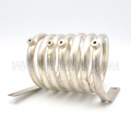
Coil's AC resistance. Theory vs Measurement

MrAl

Joined Jun 17, 2014
13,745
The clue to the discrepancy is the "At Resonance" condition. The effective impedance of a resonant circuit is much greater than the impedance of either element. So at resonance you are measuring the effective impedance of the tuned circuit, which should be much greater, as you have discovered.
To measure the "AC resistance" (REACTANCE) of the coil, disconnect the capacitor and repeat the voltage and current measurements of the coil alone.
Hi,

I am not sure you meant to imply that the AC resistance was the same as the reactance, because that's not true. The AC resistance is a completely different thing than the reactance. I think maybe you just worded it wrong.

If this is really physical resonance and not just a peaking measurement, then the only resistance should be the DC resistance plus the AC resistance, which should still be very small at 40kHz with that gauge wire. There has to be something very wrong with this setup or something like that to get more than 15 times the quantity of the measurement.
 

MisterBill2

Joined Jan 23, 2018
27,874
At one point the TS mentioned that it was a series resonance, which means that the resistance of the capacitor was also contributing to the voltage drop measured. I suggested using a parallel resonance and tuning for a peak in voltage instead of current. No response to that. Does it make sense to anybody else??
 

sparky 1

Joined Nov 3, 2018
1,218

nsaspook

Joined Aug 27, 2009
16,389
The coils AC resistance should approach zero when the Xc=Xr to find that we approximate using the information.
18 AWG. spacing 3mm apart, 50cm Dia. 50T turns, If I understand correctly give 1.23mH
Coil Inductance Calculator - Engineering Calculators & Tools (allaboutcircuits.com)
The calculated approximation using LC resonance calculator using 40kHz and 1.23mH gives C value of 12.87nF
Resonant Frequency Calculator (omnicalculator.com)
The reactance will cancel but the AC resistance is 'real' as it is the energy loss in the conductor at the frequency of interest (the cross-section for current electrically decreases) vs the loss at DC where we have the entire wire cross-section.
This reduces the usable cross sectional area of a conductor and thus, resistive losses at high frequencies increase.
 

MisterBill2

Joined Jan 23, 2018
27,874
The reactance will cancel but the AC resistance is 'real' as it is the energy loss in the conductor at the frequency of interest (the cross-section for current electrically decreases) vs the loss at DC where we have the entire wire cross-section.
This reduces the usable cross sectional area of a conductor and thus, resistive losses at high frequencies increase.
My point is, and was, that changing to a parallel resonant arrangement will put the AC reactance s in parallel instead of in series. And when they are exactly the same, except for the polarity, then calculating the value should be possible.
 

sparky 1

Joined Nov 3, 2018
1,218
Simulation of the coil in series resonance using 1.23mH, 12.87n, step response peaks at 40kHz

Running the simulation of parallel resonance shows flat line as if the capacitor and inductor are not present.

The Ltspice file " RLC-step-response-resonance-frequency-series-parallel.asc"
from archive donated by mick001

We understand AWG 18 has 6.385mΩ per foot DC however AC frequencies according to a chart given the resistance of 18AWG (skin effect)
frequency and resistivity for a given permittivity is another factor.
Wire Resistance at Various Frequencies (ve3efc.ca)
 

Attachments

Last edited:

MisterBill2

Joined Jan 23, 2018
27,874
GIVEN that we know there will be a resonance with a parallel LC circuit, it seems that the model is not correct in some manner, or that the simulation was otherwise incorrect. Perhaps the resonant frequency is a bit different?
Or perhaps the simulator simply does not know how to handle a parallel resonant circuit.

I suggest trying again but not using that same model. Just change the connections on the series LC circuit that was used for the series model. It will not be the first time that an incorrect model has provided incorrect results with a simulator.
 

MrAl

Joined Jun 17, 2014
13,745
At one point the TS mentioned that it was a series resonance, which means that the resistance of the capacitor was also contributing to the voltage drop measured. I suggested using a parallel resonance and tuning for a peak in voltage instead of current. No response to that. Does it make sense to anybody else??
Hi,

Yeah it makes a lot of sense and may turn up some info on what is going wrong here.
Need a resistance in series with the parallel LC though in case he's using a voltage source for testing instead of a current source.
 

MisterBill2

Joined Jan 23, 2018
27,874
Hi,

Yeah it makes a lot of sense and may turn up some info on what is going wrong here.
Need a resistance in series with the parallel LC though in case he's using a voltage source for testing instead of a current source.
TRUE!! Driving a resonant circuit with a current source would certainly show a response peak, though.. "Out of Sight" comes to mind.
 

MrAl

Joined Jun 17, 2014
13,745
And in spite of theskin effect, I see the RF coils in a 155 MHZ receive front end wound with number 36 or #38 wire.
Oh ok, and in power converters where the loss of energy is a major concern, I understand that #26AWG is good up to 100kHz, and that figure came from a company that specializes in stuff related to power conversion like magnetic cores, and they've been around for a long, long time.
 
Top