Facebook
 Google
 GitHub
 Linkedin
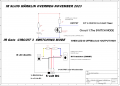
I will provide a schematic as you are correct to make everything visible.You are making it very difficult for people to help with your problem as you will not supply a schematic. From the very limitied information you have just supplied it seems that you need to hold the "trigger IC" (Which I guess may be a 4013.) in a reset condition for a few mS when power is applied. Without a schematic we can't suggest how to do that.
Les.
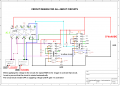
Cmos circuit is automatically switched on when applying power
- Thread starter Holz1
- Start date