classD amplifier schematic

Thread Starter

Adgj533

Joined Feb 27, 2018
21
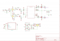
Hi guys, I am trying to build a class D amplifier at home. I got a schematic from AAC which seems to be a little complicated. I was wondering if you guys have any schematics that I can use and work with. I dont mind the power output, it could be 50W-100W.
I want a working schematic so it is preferred if you have built it or worked with.
I have attached the one I got from AAC which is designed by cezar
Thanks
 

Attachments

TechWise

Joined Aug 24, 2018
151
At a glance it would appear that the bottom comparator has its input back to front. I suspect it should be inverter so that it produces a complementary signal to the top one. This seems a pretty simple circuit containing all the main parts of a Class D amplifier. I'm not sure it's possible to make it any simpler.

You will find lots of information by googling the "synchronous buck converter" and "half bridge circuit". These circuits are basically the same as a Class D amp and will show you how the components work together.
 

crutschow

Joined Mar 14, 2008
38,334
You likely can't get much simpler for a discrete design.
And it will have some distortion since it uses an exponential sawtooth from the 555 oscillator, not a linear sawtooth, to generate the PWM signal from the audio input.

Much simpler would be to use a Class D IC, such as those from Texas Instrument.
They also would likely give better performance with lower distortion.
 
Last edited:

Thread Starter

Adgj533

Joined Feb 27, 2018
21
And it will have some distortion since it uses an exponential sawtooth from the 555 oscillator, not a linear sawtooth, to generate the PWM signal from the audio input.

Much simpler would be to use a Class D IC, such as those from Texas Instrument.
They also would likely give better performance with lower distortion.
Hi, how would I change the design to make it a linear sawtooth?
My goal is to get minimal distortion, also I am looking into the Class D IC you mentioned.
Appreciate the help
 
Top