Class D circuit implementation

Thread Starter

Hassan Wahaj Malik

Joined Oct 15, 2017
45
It may help if you put the full circuit up for us to see.
For instance, you have a NOT gate there. What is it and what are all the pin connections?
A bit like your circuit shows 1N4001G diodes but you are using MUR120 diodes.
What is your 15V supply and do you have any power supply bypassing capacitors other than the C1?
There may well be other problems that are not shown.

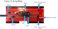
Here is the full circuit showing all the pin connections. It's wired up exactly like the circuit schematic shown except that VCC is directly connected to the power supply. I do not have the C1 connected to the VCC. I think both the power rails do not have the same ground maybe that might be the case but since it's just coming from the power supply I thought it would not make much of a difference.
This is my first ever project so I am kind of new to all of this stuff.
what other problems could there be?
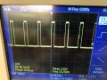
The gate driver is not outputting anything. I scoped the input to the gate driver it was a pretty clean signal but I do not get anything from the output of the gate driver, therefore, the power MOSFETs are not switching. My main concern is why the circuit is drawing so much current. in theory and the circuit simulation, everything worked fine.
 

Attachments

dendad

Joined Feb 20, 2016
4,637
You do need both power supplies to have the same ground. There is most probably the trouble.
In fact, as they are both 15V, just use the one supply. Why did you decide to use 2 separate supplies? Or maybe you are actually using one.
Even if the voltages are different, the grounds must be the same.
There needs to be a good solid short ground connection between every part of the circuit, not long leads back to the power supply.
As for the circuit, all that is there is a couple of screen shots, one of a waveform from a transistor and the other a picture of your board. No circuit diagram.
And you do need to put in some bypassing. More than just the C1 shown!
Add a 2200uF electrolytic at the board across the 15V. And a 100nF too.
And what is the NOT gate?????
 

Thread Starter

Hassan Wahaj Malik

Joined Oct 15, 2017
45
I have attached the input from the not gate (inverted input) the not gate is designed using a simple NPN transistor to invert the input signal.
I think I should use just one power supply. I have attached the circuit diagram of the vector board as well.
 

Attachments

dendad

Joined Feb 20, 2016
4,637
Does this look like what you have?
PWM-Amp2.jpg
Add the electrolytic capacitor 2200uF 35V (or something like that) and the 100nF caps if you don't have them.
Make sure the 0V and +20V connections are all the same and on the board, not long leads back to the power supply. All the connections need to be as short as practicable as long leads encourage instability.
What load do you have on this? Is it just he oscilloscope? If you are going to run a speaker, or other load, there needs to be an electrolytic capacitor in series with the output (+ve to the amp, -ve to the load) and the load is connected between the electrolytic cap and ground. Otherwise there will be DC flowing from the amp through the speaker all the time it is running.
 

dendad

Joined Feb 20, 2016
4,637
Just another note, if you are now running at 20V, that is the max logic supply voltage and you may pop the IR2010. Why not regulate the 20V down to 5V (or 12V) to run the logic side? (pin11)
PWM-Amp3.jpg

And in your wave forms, what are they? If the second (3.76Vpeak) is the pin 12 input, and the logic supply is 20V, it is not enough volts to turn on.
I think you need to put a 5V regulator for the logic supply (not 12V as in my circuit) then the 3.6V input signal may be just enough. Else you could add another transistor stage feeding the one you have, so that both inputs get the full swing drive voltage.
But do add a logic supply reg. And if you add another transistor, the 12V will be ok.
PWM-Amp4.jpg
 
Last edited:

Thread Starter

Hassan Wahaj Malik

Joined Oct 15, 2017
45
Does this look like what you have?
View attachment 139158
Add the electrolytic capacitor 2200uF 35V (or something like that) and the 100nF caps if you don't have them.
Make sure the 0V and +20V connections are all the same and on the board, not long leads back to the power supply. All the connections need to be as short as practicable as long leads encourage instability.
What load do you have on this? Is it just he oscilloscope? If you are going to run a speaker, or other load, there needs to be an electrolytic capacitor in series with the output (+ve to the amp, -ve to the load) and the load is connected between the electrolytic cap and ground. Otherwise there will be DC flowing from the amp through the speaker all the time it is running.

Yes the output fro the amplifier would go to speaker.
ill make sure to add an electrolytic capacitor.
 

Thread Starter

Hassan Wahaj Malik

Joined Oct 15, 2017
45
Just another note, if you are now running at 20V, that is the max logic supply voltage and you may pop the IR2010. Why not regulate the 20V down to 5V (or 12V) to run the logic side? (pin11)
View attachment 139159

I will use 5V as the power board i have designed can supply 3.3V 5V and 20V.

And in your wave forms, what are they? If the second (3.76Vpeak) is the pin 12 input, and the logic supply is 20V, it is not enough volts to turn on.
I think you need to put a 5V regulator for the logic supply (not 12V as in my circuit) then the 3.6V input signal may be just enough. Else you could add another transistor stage feeding the one you have, so that both inputs get the full swing drive voltage.
But do add a logic supply reg. And if you add another transistor, the 12V will be ok.
View attachment 139163
The waves are the PWM output from the MSP430G2553. ill try to implement it using 5V and the recommendations you gave me. Thanks alot for the help. Also the reisstor and diode in parallel are there for extra dead time generation but i read the datasheet of the IR2010 it already has different turn on and off delays so i decided not to add additional dead time. Would you oppose that idea?
 

Thread Starter

Hassan Wahaj Malik

Joined Oct 15, 2017
45
Just another note, if you are now running at 20V, that is the max logic supply voltage and you may pop the IR2010. Why not regulate the 20V down to 5V (or 12V) to run the logic side? (pin11)
View attachment 139159

And in your wave forms, what are they? If the second (3.76Vpeak) is the pin 12 input, and the logic supply is 20V, it is not enough volts to turn on.
I think you need to put a 5V regulator for the logic supply (not 12V as in my circuit) then the 3.6V input signal may be just enough. Else you could add another transistor stage feeding the one you have, so that both inputs get the full swing drive voltage.
But do add a logic supply reg. And if you add another transistor, the 12V will be ok.
View attachment 139163
I worked on the circuit. made the changes as you recommended. It is still drawing around 1.2A of current from the power supply.
 

dendad

Joined Feb 20, 2016
4,637
If your circuit is correct and you are not supplying the IR2010 with over volts then there is a chance you earlier popped it.
Take the FETs out of circuit and see if the current is still high.
Try to work out what part is faulty.
 
Last edited:

Thread Starter

Hassan Wahaj Malik

Joined Oct 15, 2017
45
If your circuit is correct and you are not supplying the IR2010 with over volts then there is a chance you earlier popped it.
Take the FETs out of circuit and see if the current is still high.
Try to work out what part is faulty.
Thanks for your help, I got it to work. It’s giving me a nice 15V PK to Pk output PWM.
The speaker is not playing the audio though. The analog wave looks very distorted. Do you think I should rediesgn the filter?
 

Thread Starter

Hassan Wahaj Malik

Joined Oct 15, 2017
45
If your circuit is correct and you are not supplying the IR2010 with over volts then there is a chance you earlier popped it.
Take the FETs out of circuit and see if the current is still high.
Try to work out what part is faulty.
My gate drivers keep popping up after a while. If I bring the voltage down from 20V it stops outputting.
And the speakers aren’t turning on according to the seating right now. I think it might have something to do with impedance matching but I used the formulas given in the datasheets for class D amps. My speaker has a resistance of 8ohms
 

dendad

Joined Feb 20, 2016
4,637
Can you draw the complete circuit. Not just part of it. An idea is to draw the circuit out from your board so you are more likely to catch errors. And maybe turn the board upside down from normal. That trick can help you to not just draw from memory.
Often it is really hard to debug one's own stuff as you tend to overlook things. I speak from long experience!

If you are blowing up drivers there must be something wrong. One thing that is wrong, running it on 20V is too high. That is the absolute maximum voltage.
The driver will work quite well on 15V or 12v. If it will not, you have a circuit layout error. That you need to find and redrawing the circuit from the board, no notes, can help you find it.
So, you need a FULL circuit and post it here so we can look at it for you.

Still run the FET supply on 20V, but the driver on 15 or 12V.
 
Last edited:

Thread Starter

Hassan Wahaj Malik

Joined Oct 15, 2017
45
I have attached the circuit. But the output filter should still work right for the short time the amplifier was working. So i should change the supply voltage on the gate driver to 15V?
Can you draw the complete circuit. Not just part of it. An idea is to draw the circuit out from your board so you are more likely to catch errors. And maybe turn the board upside down from normal. That trick can help you to not just draw from memory.
Often it is really hard to debug one's own stuff as you tend to overlook things. I speak from long experience!

If you are blowing up drivers there must be something wrong. One thing that is wrong, running it on 20V is too high. That is the absolute maximum voltage.
The driver will work quite well on 15V or 12v. If it will not, you have a circuit layout error. That you need to find and redrawing the circuit from the board, no notes, can help you find it.
So, you need a FULL circuit and post it here so we can look at it for you.

Still run the FET supply on 20V, but the driver on 15 or 12V.

I have attached the FULL circuit. Hope this one is clear. So the filter should still work for the short while it was working but the speaker was not outputting the sound. I have blown 3 gate drivers till now when I was trying to trace the problem using o-scope probe so I should just decrease the supply voltage to 15V?
 

Attachments

dendad

Joined Feb 20, 2016
4,637
It looks like you still do not have bypass capacitors on your supply. Change it to 12V and add 10uF tantalum cap and 100nF ceramic caps on the IR2010 supply pins, as close to the chip as you can.
Then the same for the FET 20V supply, but with an added 2200uF electrolytic.
https://www.infineon.com/dgdl/an-978.pdf?fileId=5546d462533600a40153559f7cf21200
Pages 9 and 10 stress bypassing and short leads.
Is the bootstrap cap 2.2uF? I think that may be a bit high. Try 220nF or 470nF.
Pin 13 (SD) needs to be ground, not connected to a cap.
See if that is any help :)
 

Thread Starter

Hassan Wahaj Malik

Joined Oct 15, 2017
45
It looks like you still do not have bypass capacitors on your supply. Change it to 12V and add 10uF tantalum cap and 100nF ceramic caps on the IR2010 supply pins, as close to the chip as you can.
Then the same for the FET 20V supply, but with an added 2200uF electrolytic.
https://www.infineon.com/dgdl/an-978.pdf?fileId=5546d462533600a40153559f7cf21200
Pages 9 and 10 stress bypassing and short leads.
Is the bootstrap cap 2.2uF? I think that may be a bit high. Try 220nF or 470nF.
Pin 13 (SD) needs to be ground, not connected to a cap.
See if that is any help :)
Could you actually add these to the schematic of the circuit so I do not make the mistake again, I would really appreciate it.
 

Thread Starter

Hassan Wahaj Malik

Joined Oct 15, 2017
45
Have a look at the circuit I put in post #25.
That's exactly the way had it the first time but it wasn't outputting the PWM, However, when I took out the 2200uf cap from the power supply it started to output the PWM until recently when I placed the filter on there the gate driver blew off
 

dendad

Joined Feb 20, 2016
4,637
That's exactly the way had it the first time but it wasn't outputting the PWM, However, when I took out the 2200uf cap from the power supply it started to output the PWM until recently when I placed the filter on there the gate driver blew off
That does not make sense, sorry.
Probably it was not outputting PWM but was bouncing the supply up and down and that was what you were seeing.
Have you grounded pin 13?
If I get time, I might see if I have one of these chips and build the circuit.
 
Top