Class D audio amp - university project - issue

Thread Starter

comipicaso

Joined Jan 8, 2019
7
Hi everyone,

This is my first time posting, so I hope I didn't post in the wrong section.
My friend and I have been working on a university project, where we simply choose what we want to build, and present a valid schematic from the internet to our assistants.
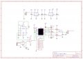
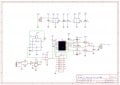
I found a circuit from the youtuber GreatScott, and ordered all the parts (I've put it in the attachment). We have changed the circuit, by adding 220nF capacitors at the inputs of the comparator, in order to eliminate the DC offset of the triangle wave and the amplified input wave. We have also put a potentiometer at the output of the LM386 as a voltage divider, in order to have a primitive volume control.

We connected all the components on breadboards, and put an 8ohm speaker at the output. The circuit worked fine when we used a function generator as the input, which was set to a 1kHz sine wave with around 500mV peak to peak. However, once we connected the input to one channel of an audio jack, which was connected to a PC (and a smartphone later on), as we slowly raised the volume, we could hear the sound, fairly distorted, for maybe half a second. Afterwards the 15V supply voltage from our lab bench power supply went into CC mode at 300mA output and the voltage dropped to around 5V. Increasing the current definetly doesn't help.

Once we lower the volume, everything goes back to normal with no output at the speaker, and as soon as we raise the volume, the same thing happens.

I have run out of ideas as to what could be the problem, so I would love to hear any advice.
I'm sorry for bothering, and I thank everyone in advance!
 

Attachments

crutschow

Joined Mar 14, 2008
34,280
It looks like you need a large capacitor in series with the speaker output to block the DC voltage from the circuit.
Since you are operating the circuit from a single supply, the average (DC) output voltage is 1/2 the supply voltage.
This will cause a large DC current through the speaker which the amp can't handle and which can damage the speaker.
Try a 2200μF or so electrolytic (plus side to the amp output).

Why are you using an LM386 power amplifier at the audio input?
All you need there is a low-noise op amp.
U1 should be a high-speed comparator such as an LM339, not an op amp, since it's being used to generate the high-frequency PWM signal.
 

Thread Starter

comipicaso

Joined Jan 8, 2019
7
Thank you for your swift reply!

I will make sure to add the capacitor tommorow, and I will update my results.
I'm still relatively new, and to my mistake, I have decided to follow the circuit diagram without giving too much thought to it.
You make a very good point, the LM386 is unnecesary, I will try to optimise the design as soon as I make it work.

As for the comparator, we are using an LM393 comparator IC, which contains dual differential comparators.
I have checked the datasheet for both the LM393 and LM339, it seems that the response times are the same for both ICs.
 

Thread Starter

comipicaso

Joined Jan 8, 2019
7
Update on the project:
Connecting the capacitor in series with the output didn't help. I though the reason for such a high current draw were the output MOSFETSs being switched on at the same time, however connecting an ammeter in series to the Vcc and the high side MOSFET, it didnt draw any current, however connecting the ammeter to the 12V supply and the Vcc pin of the driver, it is drawing 90% of the current limit of the supply, and increasing the current of the supply increases this current.
It seems that we are not driving the circuit properly, however I don't have an idea as to what could be the problem :(
 

crutschow

Joined Mar 14, 2008
34,280
The value of R6 seems a little high at that frequency.
I would go with 2kΩ or so.

Compare the two gate drive signals from U2 and see if they look correct.
Post an oscilloscope picture of the two together if you aren't sure.
 

Thread Starter

comipicaso

Joined Jan 8, 2019
7
I have compared the LIN input and the LO output on the scope, without a load connected, just a MOSFET connected to the LO and the drain connected to the bootstrap capacitors so that they could discharge and recharge to ground in order to have a valid HO signal.

The LIN and LO signals looked fine, the LO signal was voltage amplified and phase shifted a little due to the delay of the driver.
Same goes for the HIN and HO signal.

Unfortunately, I won't be able to post a scope picture until monday, I apologise for that.

Everything seems good until we connect the load, we hear sound for a few seconds, and then it starts drawing in the large current, and the lowered voltage of the supply makes it so that the driver doesn't work until we turn the supply on and off.
 

Alec_t

Joined Sep 17, 2013
14,280
Pins 2 and 13 of U2 are missing a ground connection, so the IC will malfunction.
Unusd inputs of the 74HC04 are floating, so the IC operation can be unpredictable. They should be tied to a power rail.
 

Thread Starter

comipicaso

Joined Jan 8, 2019
7
Thank you for the tip, I will do that ASAP.

I have another observation that might shed light on the issue, the first schematic from this youtuber, that we tried to build (I've put it in the attachments). It's the same principle, except that it has no preamp, and uses a potentiometer to offset the audio signal so that it has about the same offset as the triangle wave.

Upon observing the pwm generated by the comparator, everything works, up until the point that the offset is so high that the duty cycle of the pwm signal becomes almost 100%. Then the same issue occurs, the supply goes into CC mode, and nothing works until I lower the potentiometer offset and reset the lab supply.
 

Attachments

Thread Starter

comipicaso

Joined Jan 8, 2019
7
Pins 2 and 13 of U2 are missing a ground connection, so the IC will malfunction.
Unusd inputs of the 74HC04 are floating, so the IC operation can be unpredictable. They should be tied to a power rail.
Very good point, I will fix that too. Thank you! I will update on the progress as soon as possible!
 

crutschow

Joined Mar 14, 2008
34,280
uses a potentiometer to offset the audio signal so that it has about the same offset as the triangle wave.
Yes, that is necessary so that a zero input signal gives a 50% duty-cycle PWM waveform.

This is perhaps a nit, but for lowest signal distortion, the triangle-wave should be linear, not exponential as the 555 generates.
For example, the 555 can generate a linear sawtooth if the charge capacitor is fed from a PNP current-mirror constant-current source instead of a resistor.
Perhaps a task for a future upgrade. :D
 

Thread Starter

comipicaso

Joined Jan 8, 2019
7
Excuse me for my long abscence!

Pins 2 and 13 of U2 are missing a ground connection, so the IC will malfunction.
It seems that connecting the pins 2 and 13 to ground has solved the problem, and I also had to raise the current limit up to 1 amp, so that the supply voltage wouldn't drop if the IC started drawing in a large pulse of current. I have replaced the power preamp with a simple high speed, low noise opamp.

555 can generate a linear sawtooth if the charge capacitor is fed from a PNP current-mirror constant-current source instead of a resistor.
The sound did have quite a bit of distortion, and I will definetly upgrade the circuit once the project assesment is over. I will solder the components to a perfboard, because the long jumpers used on a breadboard cause a lot of noise to accumulate on the audio signal.

Crutschow and Alec_t, I sincerely thank you for your tips and advices. The project was in quite a mess as it was, and now it is starting to look like something to be proud of as a student!
 
Top