Class D audio amp TDA8920BTH

Thread Starter

Alex_H

Joined May 15, 2020
5
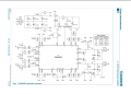
Hello, I'm really into circuits and audio, but I dont have much of a electrical engineer background, could someone help me understand whats the logics of "mode" pin circuit and how does it work? I also have reference design for it.. if not in difficulty this amplifier works as is if i connect audio input just after OPAmp circuit side if i connect input to opamp sound is nearly nonexistent
Amplifier impedance is over 100ohm so I cant measure it. And has a very distinct hum when I turn it on, would like to solve that also. Since the board is basically all smds i'd have to build an external board to control eventually all functions of mode/volume/tone.
p.s. sorry for my not PHd English ^_^ thanks in advance
 

Attachments

Audioguru again

Joined Oct 21, 2019
6,692
The datasheet for the TDA8920 shows the function voltages and delays (to avoid a POP when switching) of the Mode pin.
The opamps have a receiver module at their input that must be disconnected if you feed in an external signal. The connector from the receiver module powers the opamps with 9.3VDC, then you cannot simply disconnect the connector.
Hum can come from a poorly designed wiring layout or a defective power supply.
 

Thread Starter

Alex_H

Joined May 15, 2020
5
The datasheet for the TDA8920 shows the function voltages and delays (to avoid a POP when switching) of the Mode pin.
The opamps have a receiver module at their input that must be disconnected if you feed in an external signal. The connector from the receiver module powers the opamps with 9.3VDC, then you cannot simply disconnect the connector.
Hum can come from a poorly designed wiring layout or a defective power supply.
Hello Audioguru again, module is tecnically completely disconnected, but I was thinking that power for that opamps comes from psu (*look on screenshot*) and with tester, indeed 10v there is present or i am way off? Immagine.jpgHum is present only when no source is applied, when i connect it to any output be it pc/phone/bt reciever its fine, only white noize hiss which is normal since amp has no volume regulation
 

Thread Starter

Alex_H

Joined May 15, 2020
5
I just double checked, 10v is there, on op amp is also 10v. now, i don't believe opamp is dead, everything would die, has no damage signs as well :rolleyes:
edit: also when i short 10v rail to power: amp turns off. on mute goes full silent.
 

Thread Starter

Alex_H

Joined May 15, 2020
5
I do not understand you "when i short 10v rail to power". What is power?
It means that on the part of °reciever module° shorting 10v with °power° i get relay offline, with °mute° i get silence.. thats offtopic anyway, any ideas about that op amp and why it doesn't do what its supposed to do?
 

Audioguru again

Joined Oct 21, 2019
6,692
You do not say where you connected your audio input. Maybe your audio source is at 0VDC and it shorts the input bias voltage of the opamp causing it to not work.

If you use a capacitor to block DC but pass audio into the opamp + input then you will see and hear that the opamp gain is only 1+ (3.3k/4.7K)= 1.7 times and its output is attenuated with 6.8k to 3.3k= 0.33 times then the power amplifier IC gets only 1.7 x 0.33= 0.56 times your input signal level.
 

Thread Starter

Alex_H

Joined May 15, 2020
5
Thank you sir, then i'll compelety knock off this circuit off of the board, i tried putting in an ne5532 in place of rc4580 (function and pin compatible) still had no sound out of it, not even 50%, by the way i connect inputs here -> and use common ground on board.Immagine2.jpg
 
Top