Clap switch with latching relay

Parkera

Joined May 3, 2016
127
So now you have a “clap” waveform with a high peak voltage that tapers off to a comparatively low voltage within a few tens of milliseconds. Let’s say we feed this directly into a comparator with a 2.7 volt threshold. In the simulated waveform there are two peaks that are above 2.7 volts, which would cause multiple triggers, separated by about 1 millisecond. This would turn the light on and 1 millisecond later it would turn off. Clearly, this is not acceptable. You could raise the threshold to say 3.3 volts. That way you would only have 1 trigger per clap. Unfortunately, this is at a very high level and would be difficult to clap loud enough to ensure 1 trigger, but soft enough to not get multiple triggers. You would find that one of the two situations would happen for just about any threshold level you set.

What is needed is a circuit with a rapid charge and a controlled discharge time. One that can essentially follow the envelope shape of the waveform. In the circuit below C2 is rapidly charged through D1 by the highest peak of the “clap” waveform. C2 is then slowly discharged through R5 and D2. The discharge rate is predominantly set by the value of R5 and the value of C2 (T = RC).
upload_2017-7-10_23-40-1.png

In order to keep C2 relatively small, make R5 = 1Meg. You don’t want to make this resistor to much larger because then the input bias current of the opamp could become significant and affect how the capacitor discharges. Make C2 = 0.1uf.

upload_2017-7-10_23-41-0.png
The green trace is the output of U1. The blue trace is the voltage across C2. Notice how the capacitor charges to about 3.0 volts, even though the peak voltage is 3.6 volts? This is because of the drop across D1. By using a slightly higher gain (larger R4), some of this voltage loss can be partially compensated for. That is why I choose R4 to be 47K instead of a closer 39K. I increased the total “sweep time” to 1 second so that the full discharge characteristic can be seen.

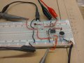
Add D1, D2 R5 and C2 to your circuit. There are many possible diodes that will work in this circuit. The 1N4148 (or 1N914) were chosen because they are common silicon switching diodes possessing a low leakage current and reasonably fast speed. If you don’t have them, feel free to try something else. Even a 1N4004 would probably work, but the charge voltage on C2 could be different.

Reproduce the waveforms on your scope with the circuit values shown and post the results. The vertical should be 0.5v/div. The sweep rate should be at a rate that will show 1 second of the waveform (100 ms/div?). Trigger the scope on the output of the opamp using channel 1. Simultaneously look at the voltage across C2 with channel 2. Put the ground for each channel at the bottom graticule. Trigger the scope on the 1st horizontal graticule.

Play with the values of C2 (anywhere from 0.001uF to 1uF) and R5 (anywhere from 10K to 1Meg), observe how different values changes the voltage across C2 with time. With R5 = 1Meg, double the value of C2 (put a 2nd 0.1uF in parallel). Measure and report how long from the trigger point it takes for the voltage to drop to 1 volt. Post that waveform also.
 
Last edited:

Thread Starter

Copey84

Joined Jul 27, 2015
198
Hi Parkera, I've been busy this week, only got back to circuit today.
Included a scope pic set up as described in post 80.

For the added components to circuit I had to go with a 910k resistor, no 1M, will order if needed though.
Used 1N914 diodes.

Will post new circuit scope pic later.1500040317172-1727321452.jpg
 

Parkera

Joined May 3, 2016
127
Hi Copey84 - I've been busy too, so I know the feeling.

The 910K is fine. It is not that much different and it is not a critical value. In time it will be the RC product that will be chosen.
The 1N914 is pretty much identical to the 1N4148. In fact, I used to use the 914 as my standard, but the majority of applications and engineers tend to use the 4148 here in the States, so I changed.

Do experiment with the R & C values in the previous post and see how it affects the voltage across C2 with time - it is an important concept to understand.

I see you are still triggering in the center of the screen. I can certainly see good information, but too bad 1/2 of the display is being wasted; it would basically double the resolution of you can trigger (or position?) more to the left. I vaguely recall some scopes are not capable of triggering all the way to the left, but yours looks like you should be able to substantially use the left side of the screen. We eventually will need to see up to 2 seconds of "sound", so try to figure out how to use the left-hand side if you can.
 

Thread Starter

Copey84

Joined Jul 27, 2015
198
Hi Parkera, I got scope pic showing capacitor charging in channel 2.
Still not sure how circuit will be more accurate to trigger though, since the amplitude of the signal varies so will the cap. Won't this still make it difficult to set comparator?
Also how does the cap discharge, does U1 provide a ground when not signalling?


1500409671255-249790750.jpg
 

Parkera

Joined May 3, 2016
127
Hi Copey84 – Before I answer your questions, some observations first. It appears that generally the circuit is working, but there are a couple of things that don’t seem right.

First is the time constant of C2 discharge. It is about 1/10th of what it should be. Are you sure you don’t have a 0.01uf capacitor in the circuit instead of a 0.1uf? Or the 910K is really a 91K? Measure these parts with your DVM and make sure they are correct (±5% for the resistor, ±10% for the capacitor).

The other thing that doesn’t seem right is where C2 discharges to. It looks like it is discharging to about 250mV. It should be discharging to the reference voltage of U1; about 454 mV. Measure the reference voltage of U1 (the + input) or across R3. It should be about 454 mV (nearly 1 division above ground); a DVM may be the best tool to use as it eliminates any scope setup errors. If the DVM measures much different than 454 mV, then check the values of R2 and R1. Or U1 could have been damaged; check that by measuring the differential voltage across the 2 inputs of the opamp (+ and – inputs). It should be less than 2mV, or simply substitute a new chip. If the reference voltage measures about 454 mV, then it is a scope setup problem, probably vertical position.

I want to make sure these two problems are corrected before moving forward.

I see that you now have the trigger point at about 4-1/2 divisions. This coincides with the “M Pos:452.0ms” at the bottom of the screen. I think this is set by the Horizontal Position control. Try setting this on the 2nd graticule (1 division from the left). That way you can increase the sweep rate to make better "time" measurements.

Now for your questions. What we have made with the addition of the diodes and RC is a kind of sample and hold circuit with a fast attack time and a slow but controlled decay time. As you can see, the various decaying peaks of a “clap” are nearly always less than the voltage of C2. They have been filtered out of the signal across C2. This by itself goes a long way toward preventing false triggering, but it will not prevent ALL false triggers. (Hint: the simple passage of time also contributes to preventing false triggering. This statement will make sense later on.) By having less “noise” on C2, it will actually make it easier to define the setting for the comparator as you will see in the near future.

You are correct about how C2 discharges. It discharges through R5, D2 and the output stage of the opamp back to ground. The opamp sinks current from C2.
 

Thread Starter

Copey84

Joined Jul 27, 2015
198
Hi Parkera, I've used a 104 ceramic cap that measures 90nF and a resistor of 912k, all within limits.
The voltage at pos input is 0.45, neg input goes between 0.45 and .46 output is 0.46.

How come I don't see any change in output with neg going higher than pos?
Thought neg should be below pos, then mic sends it high momentarily grounding U1.

The voltage across C2 is 0.23v, dropped half of U1 across D1, so not far away scope discharge value.
Included scope pic with sweep rate at 25mS

1500498202378-249790750.jpg
 

Parkera

Joined May 3, 2016
127
Hi Copey84 – The R and C look correct and the voltages around U1 are correct. I’m still puzzled about the voltage across C2 being 0.23 volts, but it is possible that my simulated diodes don’t match your actual diodes in the knee of the diode characteristic curve. That is a notoriously difficult area to simulate properly and many models only approximate that area of a diodes curve. That may also have an effect on the discharge time of C2. In any case, since there is a plausible reason for the difference and we are going to eventually tweak the RC for a specific time, we can move on.

How come I don't see any change in output with neg going higher than pos?
Thought neg should be below pos, then mic sends it high momentarily grounding U1.
I'm not sure what you are asking. When the microphone output (- input) momentarily goes below the voltage across R2 (+ input), the output will go positive (above the reference). the upper limit will be ~3.5 volts. Remember, the basic amplifier configuration is as an inverting amplifier.

When the microphone output momentarily goes above the voltage across R2, the output will go negative, but since we are using a single supply, it can't go below 0 volts (actually a few mv). That is why the negative portion of the waveform is clipped. I hope that answered your question. If not, we can revisit it.


Now it is time to discuss the comparator circuit. This stage is what will set a trigger threshold, based on the voltage across C2. Obviously the threshold needs to be greater than the expected background noise. In Post #78 I estimated that to be about 0.563 volts. And the threshold level can’t be any higher than the maximum level of the “clap”, which is ultimately limited by the saturation of the LM358. This is specified as Vcc-1.5 volts = (5 – 1.5) = 3.5 volts. We also have to take into account the drop across D1, which will be about 0.65 volts. This leaves us with about a 2.29 volt range that could work (3.5 – 0.563 – 0.65 = 2.287). It is because of the drop across D1 that I suggested the gain feedback resistor (R4) to favor the high side back in post #81.

You mentioned “clapping” softer so you don’t wake up the house at night. That would mean that the peak level runs a pretty good chance of being less than 3.5 volts. You have expressed concern over a door closing, which could easily add to the “background noise level”, as could the sound from the TV getting louder (typically during commercials). Both of these effectively restrict where the threshold can be set and still give a reliable trigger. As long as the door isn’t being ‘slammed’ shut, it is more likely the primary restriction will be on the peak of the “clap” not being high enough. For this reason, I will suggest that the threshold be set for about 1/3 of the dynamic range. (0.33 * (3.5 – 0.563 – 0.65) + 0.563) = 1.32 volts. Add the comparator stage as shown below. If you don’t have the exact values for R6 and R7, chose a combination that will give you about 1.3 volts across R7, although R6 likes to be 1Meg or less with this kind of opamp.
upload_2017-7-19_22-54-28.png

Hang in there, we are almost done, but the RC has to be optimized first. I believe you have a “2-channel“ scope (not a 4-channel). But have no fear; in reality you actually have a 3-channel scope, which is just what we need. The 3rd channel is called “External Trigger”. Yea, I’m going to force you to learn how to use that next.

You will need a 3rd “probe”, but it can be a simple piece of 50-ohm coax (RG-52) with a BNC on one end and alligator clips on the other end. Length is not critical, but generally cable probes are 3’ (1-meter) in length. The alligator clips are usually connected to the coax with about 6” (15 cm) of flexible wire. They can be purchased or made.

So far, you are used to triggering on channel 1 while you look at channel 1. You have also learned to look at channel 2 in time relationship to channel 1. These are the general steps to use the Ext. Trigger input as a 3rd channel for this circuit. You may have to read the book too.
  • With your new 1X scope probe connected to Channel 1, look at the signal you want to trigger off of. In this case, it will be the output of the opamp.
  • Set the positive-going DC trigger level to just over the baseline reference of the opamp (about 0.6V). The scope should trigger when you clap and the waveform should be familiar.
  • Move the probe to the “Ext. Trig” connector. Select “Ext. Trig” from the trigger menu.
  • Set up the trigger for positive-going, DC coupling.
  • Set the trigger level to the same level you did above (0.6V).
  • The scope should trigger when you clap. With no input on channel 1 or 2, your only indication will be the trigger light will flash. (Or you can connect Channel 1 to the output of the opamp also and look at the signal. Just make sure you are not triggering on Channel 1.))
  • Connect a scope probe to Channel 1. Look at the voltage across C2. It should look the same as what you have been seeing across C2.
  • You now have Channel 2 available to look at a 3rd signal. In this case, look at the output of the comparator.
When you get used to using External Trigger, post a screen shot of C2 voltage and the comparator output when triggered by an external trigger. It should look something like this.
upload_2017-7-19_23-7-43.png

The green trace is the voltage across C2. The blue trace is the output of the comparator. Notice how the comparator output goes low when C2 voltage crosses the threshold voltage set by R6 and R7. The time that the comparator changes state will be different for your circuit because it appears that the discharge of C2 is different with REAL diodes as discussed in the beginning of this post.
 

Thread Starter

Copey84

Joined Jul 27, 2015
198
Hi Parkera, I've got resistance values needed for comparator and another scope probe to use for ext trig.
Used the second set of outputs on lm358, followed your instructions but I'm now getting a square wave on output of comparator.
Isn't it supposed to be similar to previous readings?
1500567835929-1731396889.jpg Also I understood your explanation in previous post about amplifier setting, thanks.
 

Parkera

Joined May 3, 2016
127
Hi Copey84 - That is exactly what it is supposed to be. U2 is a comparator circuit, which means that it is running open loop. If you check the specs of the opamp, it has a 100dB open loop gain. That means that the differential input signal is amplified by 100dB, which is 100,000 times. It doesn't take much signal to drive the output into saturation and hit the supply rails (the ultimate limit).

Practice looking at the C2 voltage and the comparator output simultaneously on the scope. I will be back later tonight for "another installment". Post a photo of both signals, I will know you have read this post.
 

Parkera

Joined May 3, 2016
127
Hi Copey84 - I know you are in a hurry, but we need to be looking at the same waveform (essentially) with the same reference points in mind. The circuit seems to be working well, but with the way the scope is set up, you can't analyze what is going on in the circuit. So that we are on the "same page", please take more care in setting up your scope - ask yourself “why does it look that way?” Understand what you are looking at. I'm trying to lead you through this as best I can, but I don't have your scope or the circuit in front of me. What I see is:
  • Channel 1 = 500mv/div - good
  • Channel 2 = 500 mv/div - good
  • Main Sweep Rate = 25 ms/div - good
  • Ext. Trigger appears to be set for a rising edge (good), but with the level set for minus 600mV (bad). The level should be set for +600mV.
  • The horizontal position is set for 24 ms (bad). Why the ‘odd number’? Unless you are using the position to make a measurement, it is conventional to set it on a major graticule. This makes it easy to make a quick measurement mentally just by looking at the scope. I keep asking for you to set it on the 1st graticule on the left hand side of the screen so that we can actually use most of the display for making measurements and not cramp ourselves to the right half.
  • I have no idea why the scope appears to be triggering after the event you are trying to analyze, which is how the comparator ultimately responds to an audio stimulus (a "clap"). There are times when pre-trigger information is needed, but this is not one of them.
  • I also don’t know why the trigger point is 24ms before the center graticule, although I will admit that I’m not well versed in the latest generation of digital scopes.
Unless you know why and where the scope is triggering, it has little value as a tool to help you understand what is going on in the circuit. Let's back up a few steps. Please do the following and post scope photos at the completion of each step.

Step 1:
  • Look at the output of U1 with a probe connected to Channel 1, 500mV/div, DC coupling. Vertical position at the bottom of the screen.
  • Trigger on Channel 1, rising edge, + 600mV
  • Set the horizontal sweep to 25ms/div
  • Set the horizontal position so that the "T" near the top of the screen is at the 2nd vertical graticule (1 division from the far left). “M Pos:” should read 25.00ms.
  • Post a photo so that the scope settings can be read (sometimes there is too much glare). You should see just the offset and clipped "clap" waveform, starting 1 division from the far-left of the screen. (About like Post #82, but at the left side.)
Step 2:
  • Continue to look at the waveform on Channel 1 with all of the same settings as above.
  • Look at the voltage across C2 with a probe connected to Channel 2, 500mV/div, DC coupling. Vertical position at the bottom of the screen.
  • Set up the scope so that both waveforms are displayed simultaneously. It should look something like Post #86, except starting 1 division from the far-left of the screen (same as above).
  • Post a photo.
Step 3:
  • Remove the Channel 1 probe and connect the Ext. Trigger probe to the output of U1 instead.
  • Set the trigger for Ext. Trigger, DC coupled, rising edge, +600mV.
  • Keep the horizontal sweep set to 25ms/div.
  • Keep the horizontal position so that the "T" near the top of the screen is at the 2nd vertical graticule (1 division from the far left).
  • Look at the voltage across C2 with Channel 2, 500mV/div, DC coupling. Vertical position at the bottom of the screen.
  • You should see just the C2 waveform starting 1 division from the far-left of the screen. (Channel 1 will be a straight horizontal line at ground.)
  • Post a photo.
Step 4:
  • Connect the Channel 1 probe to the output of U2, 500mV/div, DC coupling. Vertical position at the bottom of the screen.
  • Triggering should remain set for Ext. Trigger, DC coupled, rising edge, +600mV
  • Keep the horizontal sweep set to 25ms/div
  • Keep the horizontal position so that the "T" near the top of the screen is at the 2nd vertical graticule (1 division from the far left).
  • You should be seeing both the output of the comparator (on Channel 1) and the voltage across C2 (on Channel 2).
  • You should see the waveforms all starting 1 division from the far-left of the screen with a relationship similar to Post #90, except the trigger "T" will be on the 1st division. I believe "M Pos:" should read 25ms.
  • Post a screen shot.
That's enough for now. You should have 4 clean screen shots in your next posting. Please identify each photo with what you are looking at, i.e. "Step 2, Channel 1 on U1 output. Channel 2 on C2".
 

Thread Starter

Copey84

Joined Jul 27, 2015
198
Hi Parkera, I've got the four scope pics you requested with adjustments made.
I was setting ext trig the same as channel trig, but with 0v ref at bottom of screen it was showing a neg voltage.
Ext now set in positive.
Pics start with step one at bottom. Bit odd, but it's the way they uploaded.

15006396854031716308007.jpg 1500637026426-832801354.jpg 1500638801333-249790750.jpg
1500636621862-1731396889.jpg
 

Attachments

Parkera

Joined May 3, 2016
127
Hi Copey84 – Those look good. The reason for the progression of tests is so that you could see
  • How the signals in the circuit are processed.
  • How to set up and use Ext.Trigger on a scope. It is such a wonderful feature of scopes, going back to day 1, but hardly anyone ever uses it. Admittedly, the modern scope does such a good job of triggering off of the signal that Ext. Trigger is hardly ever needed, but when the need does arise, you don’t normally think of using it (because you never do use it – kind of a catch22).
I hope you understand how the “clap” sound is processed through the circuit, because a good understanding of that will enable you to understand the characteristics of that processing. I will comment on the comparator later. For right now - The key action to understand is the charging and discharging of C2.

Your 3rd photo (2nd one posted) shows that action. To use a “digital term”, D1 and D2 are steering diodes. In theory they act like switches with no loss. In reality there are losses in the form of voltage drops across them.
  • Charging will occur whenever the output of U1 exceeds the voltage on C2 plus the forward voltage drop across D1. Charging current is supplied (and limited) by the ability of U1 to source current; specified at 40mA typical. Since the current through D1 is “relatively” high, the voltage drop will be the typical forward drop we are taught in school for a silicon diode – ~ 0.65 volts. If you expand the leading edge of C2 charge (by setting the time base to about 5ms/div) and also look at the output of U1, you will see that C2 is likely charged in 2 or 3 steps corresponding to the peak of the individual waveform peaks. (Now you know why I wanted the waveforms to be at the far left.)
  • Discharge of C2 begins immediately after the output of U1 becomes less than the voltage on C2. However, since the discharge path is through R5, the current is limited by the value of R5, which is around 2-3uA. The result is the discharge time is around 16,000 longer than the charge time. That is why you see a long slow decay and the rise time ‘looks’ instantaneous. This longer discharge time also enables C2 to be charged to higher levels with subsequently higher waveform peaks (up to the limits imposed by the supply voltage and the opamp).
  • You will notice that the waveshape of C2 discharging nearly tracks the decaying peaks of the “clap” waveshape (the envelope defined by the positive peaks). In addition, C2 discharge voltage is also nearly always above the “clap” envelope.
Now we will turn our attention to the comparator circuit. Looking at the 4th photograph (1st one posted), you will notice that the comparator output goes high pretty much immediately at the start of the “clap” (remember, C2 charges at that point). It remains high until the voltage across C2 drops below about 1.35 volts, which is just about what the threshold of U2 was set to (1.33 volts nominally). Regardless of the level of the “clap” waveform, as long as it is above 1.33 volts, the output of the comparator always goes at least to 3.5 volts and remains there until C2 drops below 1.33 volts, thus making a nice square-wave pulse. The comparator circuit is a 1-bit A/D converter.

Don't jump to the end yet.

So the circuit we have right now is a pretty good circuit with reliable triggering from a “clap”. BUT . . . Here in the States a product called The Clapper used to be marketed on TV. In order to make it an ‘up beat’ commercial, they ALWAYS used 2 claps, timed to the music, to turn on or to turn off the light. It was a catchy commercial and The Clapper has become almost part of the language, and is always described with 2 claps by those old enough to remember the commercial. The point of this is that, at least over here, most people will routinely clap twice in rapid succession. The circuit needs to work either way though.

What is “rapid succession”? That varies quite a bit with the person. The commercial was around 0.2 seconds between claps, but most people, if they are not aware of the commercial, will find it more natural to allow 0.3 to 0.4 seconds between claps. Extending the time to 0.5 seconds seems artificially slow, at least to me. In other words, “rapid succession” is quite subjective.

I have recorded two “claps” and edited the recording so that the claps are spaced 0.2 seconds apart. I also increased the overall display time to 1 second. For you to see that amount of time on your scope, you will need to set the sweep time to 200ms/div. Let’s see what happens when you clap twice with the circuit as it is right now.
upload_2017-7-21_23-36-8.png
In all plots, the red trace is the output of U1. The blue trace is the voltage across C2. The green trace is the output of the comparator.
Notice you get two very nice pulses out of the comparator. The first "clap" would turn on the light, and 2/10 of a second later the 2nd "clap" would turn off the light. The circuit responds to the "clap" very nicely, but it responds too fast.

How can we slow it down? We can increase the RC time constant of R5/C2. That way it will take longer for the voltage across C2 to discharge below 1.33 volts. R5 is already at 910K, which is about as high as we like to have with the opamp we are using. Let's arbitrarily increase the size of C2 by 10 times. Lets first see how it responds to 1 clap.
upload_2017-7-21_23-58-23.png
Notice that the comparator pulse width increased 10 times to just under 0.4 second. And now with 2 "claps", spaced at 0.2 seconds.

upload_2017-7-22_0-2-48.png
Notice the comparator pulse width increased to about 0.6 seconds, but still a single output pulses even with two input "claps". We have now given the circuit the ability to handle a natural "double-clap" by increasing RC time constant.

This circuit can handle multiple “claps” well because C2 charges very rapidly to a peak that is above the reference of U1. If another “clap” comes along before C2 can discharge to the threshold of the comparator, it simply extends the time that C2 voltage is above the threshold of U2. The action of automatically extending the discharge time provides further immunity toward false triggering. Below is a table of simulated pulse widths vs. "clap" spacing. In your case, C2 is now equal to 1uF.

2 claps, 0.2 Seconds apart: Pulse output of U2 = Single Pulse, 0.6 seconds
2 claps, 0.3 Seconds apart: Pulse output of U2 = Single Pulse, 0.7 seconds
2 claps, 0.4 Seconds apart: Pulse output of U2 = Two Pulses. See waveform below
upload_2017-7-22_0-20-13.png

From these simulation experiments, you probably want to make C2 = 2.2uF. That way the circuit should be able to handle double-claps up to about 1/2 second, which will give a pulse output of somewhere around 1.5 seconds. If 2.2uF is a bit too long, R5 can be decreased in value to "fine tune" on/off delay time. It is unlikely that it would be important to turn a light off 1.5 seconds after you turn it on. Of course, these times are subjective and ultimately you just have to try it.

Try increasing the value of C2 and, if necessary, decrease R5 and get a feel for the response by looking at the pulse output of the comparator. Increase the sweep time so that you can see 2 to 5 seconds of total time. Ideally, C2 should be a good ceramic or Tantalum capacitor. Conventional aluminum electrolytics will work, but generally make poor timing capacitors because of their wide tolerance (+80%, -20% is typical) and because of their leakage (in this circuit they will effectively look smaller), which is very temperature and age dependent.
 

Parkera

Joined May 3, 2016
127
Hi Copey84 – The difference in C2 discharge between my simulation and your actual circuit has continued to bother me a bit, and then it occurred to me why. So far, all of the measurements you have been making have been with a 1X scope probe, which has an input impedance of 1 Megohm. When I added a 1Meg resistor across C2 (simulating a scope probe), I got the same timing and voltage measurements that you have been getting. I should have thought of that sooner. It just goes to show that simulation can accurately predict performance IF your simulation model is complete and accurate.


For the simulated timing plots I posted, I actually changed the value of C2 to match the timing from your circuit. I think the simulated C2 was 0.763uF. The exercise and results are correct, but the value of C2 was being influenced by a 1Meg scope probe across it.


So now my recommendation is for C2 to be a 0.47uF with a 910k (or 1 Meg). That means that the circuit will treat “double-claps” up to about 1/2 second apart as a single “clap”. Any longer than that will result in the light turning on then turning off (or off then on, depending on what state you are in).
 

Thread Starter

Copey84

Joined Jul 27, 2015
198
Hi Parkera, I changed cap and did the double clap about half a sec in-between as instructed.
From the scope pic you can see the comparator turn on then off, instead of remaining on.
Was thinking of increasing C2 to so that comparator remains on between claps, what you think?1501066697649-1731396889.jpg
 

Parkera

Joined May 3, 2016
127
Hi Copey84 – From your scope pic I see the following:
  • Your timing of ½ second is just about perfect. Your scope setup is very good also.
  • The first “clap” was not as loud as the 2nd “clap”. I can tell this by looking at the peak voltage C2 charged up to.
  • The trailing edge of each pulse occurs at exactly the same voltage on the C2 discharge curve, which is right where the comparator threshold is set; 1.33 volts.
  • Because C2 peak voltage for the 1st “clap” (2.4 volts?) was less than that of the 2nd “clap” (3.6 volts?) , the time it takes for C2 to discharge down to 1.33 volts from its peak is less for the 1st “clap”, therefore is the cause of the shorter pulse width of the 1st “clap”.
Your logic of increasing C2 is good, but you haven’t figured out the root-cause of the short pulse width yet. Please re-read and understand Post #94, then perform this experiment, not before.
  • Connect Channel 1 probe to the output of U2.
  • Trigger on Channel 1, rising edge.
  • Connect the Channel 2 probe, set for 1X, across C2 (viewing the signal at C2 is optional).
  • Measure the pulse width at the output of U2 with a single “clap”.
  • Now set the Channel 2 probe to 10X.
  • Measure the pulse width at the output of U2. See the difference?
  • Remove the probe from C2.
  • Measure the pulse width at the output of U2 again. Do you still see yet another small change in pulse width?
What you are seeing is the loading effect of the scope probes on the operation of the circuit. The standard input impedance of an oscilloscope is 1 megohm, shunted by a small capacitance, typically around 20 pf. A 10X probe has a standard input impedance of 10 megohm, shunted by a much smaller capacitance, around 2-3 pf. There are 100X probes with a 100 megohm impedance, but they are much less common.

Obviously a capacitance of 20 pf won’t make much difference to a 0.47uF capacitor, but the 1 megohm resistance in this circuit will have two effects. The first is it becomes a shunt path helping to discharge C2 quicker than R5 alone, and second, it forms a voltage divider with R5 that affects what C2 can discharge to (which also has an effect on discharge time). Don’t ask for an explanation of how, you would have to get into Thevenin equivalents for the circuit consisting of U1, D2, R5, C2 and the scope probe. Even measuring the ‘baseline’ voltage of C2 after full discharge with a 10 megohm input will give an error of about 0.2 volts (the nice thing about simulation is all measurements are completely transparent as far as affecting the circuit operation).

The circuit surrounding C2 is a “sensitive” circuit, meaning that it is readily influenced by any form of loading or pickup of external fields. That is why, in the circuit, it is ONLY loaded by the input impedance of the LM358, which is somewhere around 100 megohms. (You would never amplify this signal with an inverting-configuration amplifier because of the much lower input impedance.) When you do your final layout, make sure that the C2 node wiring is VERY SHORT and compact, but spaced relatively far from other traces.

The reason you don’t have these effects when you look at the output of U1 or U2 is because the output impedance of an opamp is very low, less than 100 ohms, so the effect of 1 megohm across 100 ohms is minimal (but not non-existent!). When you are “fine-tuning” the value of C2/R5, it is best to look at the pulse width generated by U2 because all ‘stray’ factors affecting the pulse width are taken into account.
 

Thread Starter

Copey84

Joined Jul 27, 2015
198
Hi Parkera, i was able to get the pulse width duration to 550ms when scope probe was removed from C2.
However I'm still confused though, why the double clap in quick succession?
If I clap once the circuit either comes on or it doesn't, if not I try again, with a few seconds in-between.
As I understand from your posts the two claps are sending the comparator high then low then high again.
Can't this be avoided by just doing a single clap?
 

Parkera

Joined May 3, 2016
127
Hi Copey84 - Very good on the 550 ms. I assume you can appreciate how connecting a probe to a circuit can alter its performance. I remember going through similar exercises early during my training and periodically during throughout my working career.

The whole "double-clap" thing is just recognizing that many people will 'instinctively' clap twice, and you would want the circuit to work for them also. It certainly will work fine with a single clap.

In fact, I first test the circuit with a single "standard clap", then try it with different types of single claps, double-claps with different times between the claps, claps with background music/noise and claps with conversation in the room. I have also tested it with sounds other than claps. I do all this to optimize the circuit and so i have some assurance that it will work under a variety of conditions and also to learn what the limitations and constraints exist.

I learned a long time ago to thoroughly test the breadboard with just about every conceivable kind of normal operation. The prototype(s) gets the same testing plus what ever else you can dream up, followed by complete operation to specification under various environmental conditions. Pre-production units (typically 10 to 25 units) are fully tested to specification under a limited set of environmental conditions and placed in the field for a period of time with full monitoring. Production units are tested for key parameters at room temperature and sometimes at temperature extremes (depending on type of product). And with all this testing, the customer ALWAYS comes up with surprises you didn't anticipate.

I don't expect you are going to put this into production and sell it (if you are, please cut me in for a percent of the profits), but it never hurts to completely check a design, at least within practical limits for a one-of.

Let me know if you are comfortable with the circuit up to the point of the comparator output, or if you have any more questions before moving on for the rest of the circuit.
 

Thread Starter

Copey84

Joined Jul 27, 2015
198
Hi Parkera, I get that the scope probes are loading the circuit and therefore having an effect on results.

I agree it's best to test circuit while on breadboard to save any problems later on.

Still unsure about comparator though. If someone did a double clap and the comparator goes high on first clap, the circuit must then remain on after the second. So how come I see two separate outputs on my scope which means on off.
Thought I should get a continuous square wave from comparator like your SIM in post 93, regardless of scope probe effects.
 
Top