Clap switch with latching relay

Parkera

Joined May 3, 2016
127
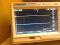
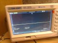
Hi Copey84 - That kind of "high frequency" noise and its amplitude are expected. It won't be a problem at all. In photo #2 I notice an increase in the level starting at about 2.5 mS (5th division). It almost looks like power supply ripple. Do you also have it on the supply line? Try putting a 270 ohm resistor across the 5V line as it comes in to the breadboard and see if it goes away.

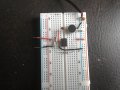
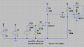
I really would like to know the DC voltage at the output of the microphone.
 

Thread Starter

Copey84

Joined Jul 27, 2015
198
149876889260675544571.jpg 1498771701156-1693114157.jpg Hi Parkera, I tried the 270ohm resistor across the supply but no real change.
The voltage at the mic is 2.68V.
I've included scope pics of signals at supply input and at mic. First pic shows signals with no load, second pic shows 270ohm resistor in play.
Channel 1 is the mic, 2 is at the supply.
 

Attachments

Parkera

Joined May 3, 2016
127
Hi Copey84 - I don't see the same "low frequency" noise on your new pics, so that eliminates my guess at power supply fluctuation as the cause. It was probably some sound in the room (even sub-sonic) that was not evident. In my early engineering tech days I was taught to explain every nuance in a waveform. Most of the time it didn't make any difference, but until you KNEW what was the cause, you could not make the statement that it didn't make any difference.

Thanks for the DC voltage at the mic. It lets me know where the operating point of the internal FET is. It appears to be near ideal.

Now that the microphone operating point has been established, the next step is to capture typical waveforms. To make this easier, I would like you to add a standard opamp 10X inverting amplifier to your breadboard. The input resistor is actually the 10K mic bias resistor, so the feedback resistor should be 100K. The LM358 is a dual-supply type opamp, so the + input needs to be biased at 1/2 supply voltage. Do this by connecting a 100K to ground and another 100K to +5. The amplified waveform will be centered at 2.5 volts. This is what the circuit should look like. The value of C1 can be anything from 0.01uF to 0.1uF. Let me know which value you end up using.

upload_2017-6-29_21-33-49.png

For these next tests I want you to capture the sound of a "Clap" on the scope as seen at the output of the amplifier. Set the scope up for 2V/div, DC coupled. Adjust the vertical position so that 2.5V is in the center. Put the scope in the triggered sweep mode (not auto). The trigger level will have to be played with, but it will probably be somewhere around 2.7V, DC. The sweep rate will depend somewhat on the amount of echo in the room, but will probably be about 20 ms/div for a total displayed time of 200 ms. (I want to see the full decay of the "clap" until it falls into baseline noise.) Use the delayed sweep feature so that the trigger point is about at the 2nd division. All of these settings are my best guess for a starting point. Take some time to look at various "claps" and how they can differ from each other. What I would like to see would be something similar to this waveform.

upload_2017-6-29_21-53-5.png

Once you can acquire the sound of a "clap" so that it looks similar to the above and learn what a typical "clap" looks like, I would like to see waveforms for the following conditions:
  • A very loud clap, very close to the microphone. - this gives the maximum output likely to be seen from the microphone under any condition.
  • A typical clap where the final locations are expected to be (both the microphone and the person doing the "clap" should be in their respective locations). - this gives the normally expected level from the microphone.
  • In order to get an idea of the general environment this circuit has to work in (acoustically), I would like to see a screen shot of normal background noise in the room (radio/tv on, people talking in the room or nearby, etc.) The mic should be in its final location. Make this a longer sampling period, say 1-2 seconds total. For this test the scope will need to be in the Auto sweep mode.
Hint: Once you get a waveform you want to photograph, "freeze" the display so that you don't accidentally trigger the scope again from some sound picked up by the mic.
 

Thread Starter

Copey84

Joined Jul 27, 2015
198
1499110533402712650012.jpg Hi Parkera, I got back to building the circuit as described in your previous post this evening.
The value cap used is a 0.1uF ceramic type.
Still new to scope trig functions, but between having read through instructions and pressing buttons I think I've got a signal that looks similar to yours. Included photo.
This signal was taken at workbench in quiet surrounds, going to set scope up in room where circuit will eventually be used so if it's set up wrong let me know.
 

Attachments

Parkera

Joined May 3, 2016
127
Hi Copey84 - Don't move your setup yet. I have to go back to earlier posts and study your scope. I will respond in more detail later tonight or tomorrow.
 

Parkera

Joined May 3, 2016
127
Hi Copey84 – I want to confirm what I am seeing on your scope.
  • It looks like Channel 1 is displayed twice, but in different colors. Is one the “main sweep” and the other the “delayed sweep”? Are these labeled “M” and “W” at the bottom, center?
  • It looks like there are 16 vertical divisions TOTAL. Is one half for the main sweep and the other half for the delayed sweep?
  • It looks like your scope has 18 divisions horizontally. Is this correct?
Perhaps I should have used the term “Delayed Trigger”. What I was looking for was a single waveform with a trigger point located about the 2nd division horizontally. Current design of digital scopes tends to put the trigger point in the middle of the screen by default, which is OK. I just like using most of the screen to show the waveform, and only devote a small portion toward seeing what is happening BEFORE the trigger point. I guess it is a throwback to analog scopes where the normal trigger point was at the far left, and having the ability to see what happened before the trigger was a new and novel idea only available in a digital oscilloscope (brand new around 1977).

But moving on – assuming the above assumptions are correct. From the info at the bottom, Channel 1 is DC coupled and set for 2V/div. The trigger is set for the rising edge at 2.72 volts. The sweep rate is 25ms/div. These are good settings.

Looking at the (top) trace, it looks like the amplifier is saturating (approximately) at 0 volts and 3.8 volts(?). This would be about right for an LM358 running on a 5V supply. The decay, after the circuit comes out of saturation, looks like a typical “clap” waveform.

Let’s do a little more work in your workshop before moving into the actual room for measurements. First, let’s work on the scope setup.
  • Set the vertical up for 1V/div on Channel 1, DC coupling. Position ground 1 division up from the bottom.
  • Keep the trigger level at about where it is now (2.72 volts but not critical).
  • 25ms/div is a good sweep speed for now. Set the trigger position for the 2nd division. (The red trigger arrow in the small trigger graphic at the very top margin will move toward the left, but still be within the area bracketed by the solid horizontal bars. The “T” symbol, currently at the center graticule will move to the 2nd division.) That will give 50ms of pre-trigger information and 400ms of post trigger information.
Next, try moving away from the microphone some so that a typical “clap” does not saturate the opamp, but still gives a positive peak close to 3.5 Volts for a couple of “cycles”. Look at the waveform I posted for reference, but expect a lot of variation in the details every time you clap. Let me know about how far you are from the microphone under these conditions and post a waveform.

Without any circuit changes, (but possibly adjusting the scope TRIGGER LEVEL) move away from the microphone by about the same amount you expect to be in the final installation (i.e. 3 meters). Post that waveform too. Note you are still in the workshop.

I notice your scope has a USB port on the front. Is it possible to save a waveform from there and post it? If you can, that would save the camera step and eliminate distortions. If not, don't worry about it.
 

Thread Starter

Copey84

Joined Jul 27, 2015
198
These are best I could get Parkera.
Followed your last instructions and set up scope although I'm still not sure it's correct.
First pic was taken 2m away from mic instead of 3, not much room surrounding work bench.
The second clap was directly over mic.

149919826957575544571.jpg
1499198130070876405468.jpg
 

Attachments

Last edited:

Parkera

Joined May 3, 2016
127
Hi Copey84 - OK, this is looking good. The clipping of the positive but not of the negative half at 2m indicates the mic has a pretty high sensitivity. Try the same experiment using a gain of about 3.3 instead of 10; make the feedback resistor a 33K. This will make it easy to add signal conditioning circuitry while at the bench. We will adjust this resistor again later on.

For right now, find the combination of distance from the microphone and how loud you clap that substantially reproduces the whole waveform without significant clipping (not more than 2-3 ms at the beginning). If you find that a 47K works better, go ahead and use it instead of a 33K. Just let me know what value you settle on.

This is an important point - The total "envelope" of the waveform should be approximately symmetrical, meaning that both the top half and the negative half of the waveform (ref to 2.5 volts) should be roughly a mirror image of each other and look about the same. This “envelope” will have a steep or fast "attack" and an asymptoticdecay”. The front edge of the envelope should not have more than 2-3ms of clipping visible on either the positive or negative half of the envelope.

If you aren't sure of what I mean by the "envelope", envision a smoothed line connecting only the peaks of the total "clap" sound; that is the "envelope" of that sound. Think of the modulation envelope of an AM modulated RF waveform.

The scope setup is about right. If you can figure out how, move the trigger point to the 2nd horizontal graticule.

Please post your "linear" waveform of a "clap" and let me know what you use for a feedback resistor value.
 

Thread Starter

Copey84

Joined Jul 27, 2015
198
Hi Parkera, I replaced the mic bias resistor with a 3.3K and the feedback with a 33K as described in last post.
From 2M distance I got the waveform below, I've also included second waveform with 47K feedback resistor and 3.3K in circuit. Think the 47K produces more symmetry between these two pics this time, but don't think it would be the case every time. Variation in clap is the reason I think.
1499282788586712650012.jpg
14992829798962078401373.jpg
 

Parkera

Joined May 3, 2016
127
Hi Copey84 - Remember, the 10K bias resistor is cast in stone. DO NOT CHANGE IT.

Please re-do the experiment with the 10K bias resistor. Right now, you are ONLY changing the feedback resistor, with the goal to amplify the "clap" waveform without clipping of either the positive or negative portion. You should have peaks of +3.5V and +1.5V (+/- 1 volt referenced to 2.5 volts).
 

Thread Starter

Copey84

Joined Jul 27, 2015
198
Hi Parkera, i put 10k back in circuit and with 33k as feedback resistor I got scope signal in first pic.
Changed 33k to 47k and got second scope pic below.1499374127291712650012.jpg 14993744124872078401373.jpg
 

Parkera

Joined May 3, 2016
127
Hi Copey84 – Thanks for re-doing the test. There is still some positive saturation, even with the 33K, but it is close enough for me to make the necessary estimates.

If there was no clipping involved at all, the + peak is ~ 4.3 volts.

I believe I was wrong about assuming the input resistance to the amplifier was the value of the bias resistor – I think it is the value of the bias resistor in parallel with the equivalent resistance of the FET channel. I suspect the amplifier input resistance is closer to 5.5K to 6K, making the actual gain more like 6 or so. This would make the peak microphone output about 300 mV. The correct way to estimate it would be to do a CURRENT analysis of the stage and work backward, but that gets into a lot of math. The exact gain of the amplifier really doesn’t make much difference since the output from the microphone will be different each time you clap. We will base the rest of the circuit design on a (linear) peak voltage of 4.3 volts.

Since my “clap” is similar, but different than your “clap” (and I don’t have your exact microphone or room), I have elected to do some simulations using LT-Spice instead. This will allow us to move forward with a bit better efficiency also. This is why I needed the bias resistor locked down and the waveform to be very linear and not clipped on either the positive or negative halves. By the way, my simulations will show an LM324 instead of an LM358. As you probably know, the LM324 is a quad opamp version of the LM358. It was the first low-power opamp and the output characteristics of the LM358/LM324 are a bit lacking compared to more modern opamps and are important to account for in this application.

The first thing I did was to record a typical “clap” with the computer microphone and sound card and save it as a WAV file. (This is how I posted the earlier waveform.) I can import this into LT-Spice and it to define the voltage source instead of your typical sine wave. I can make circuit changes based on an actual “clap” waveform and see what those changes alone will do. Since you have demonstrated a similar "clap" waveform, the simulation should be sufficiently close. KEEP IN MIND - THERE WILL BE DIFFERENCES, but do try to be consistent with how you clap.

Next, I simulated an electret microphone (V2, R10, R9, V3, J1) with the 10k bias resistor (R1) so that the DC output was the same as what you measured. I adjusted R9 (below) until I obtained a similar positive peak at the output of the opamp as what you obtained (Post #71, first trace). Since the LM358 output stage can only go to the + supply voltage -1.5 volts, I prevented clipping by temporarily raising the Vdd to the opamp ONLY to 10 volts. This is what I am working with at this point. Except for the simulated microphone components, you should be working with the same circuit.

upload_2017-7-7_0-10-2.png
 

Attachments

Parkera

Joined May 3, 2016
127
All rooms have a degree of background "noise". I need to get some idea of how loud that noise is. It would help immensely if I knew why you want to build the circuit and who will be using it. Also, tell me what kinds of activities usually go on in the room. That tells me if significant variations can be expected or if I need to ask more questions. You will need to bring the circuit and scope to the room where it will be used.

I need to see a screen shot of a “clap” waveform under the following conditions with the circuit in Post #72.
  • In a quiet room, I need to see a typical clap where the final locations are expected to be (both the microphone and the person doing the "clap" should be in their respective locations).
    • Set scope ground up in the middle of the screen.
    • Use AC coupling.
    • The sweep rate should be 25ms/div as you have been doing.
    • Adjust the vertical range so that the peak is AT LEAST one division, but less than 4 divisions.
    • Adjust the trigger level as required.
Next I need to see what the background noise looks like with the SAME VERTICAL SETTINGS.
  • The background noise should include radio/tv on, people talking in the room or nearby, etc., whatever is typical.
    • Keep the circuit/microphone in the same location as above.
    • Keep all vertical settings of the scope the same. (The noise level could be less than one division during this test.)
    • The sweep rate should be set to give at least 2-5 seconds of acquired room noise. (Sorry, I don’t know what sweep speeds your scope can go down to.)
    • Set the scope to Auto Sweep Mode.
    • Since only a sampling is required, “freeze” the display after you get the sample you want. Preferably it should include the “peak” background noise.
DO NOT CHANGE ANY CIRCUIT VALUES from those listed in Post # 72 regarding the amplifier or microphone bias resistor. Please make sure you provide ALL information asked for in this post. It includes both usage information and 2 screen shots on location. Please read and understand what is required and being asked for before posting information. If you have any questions understanding what is being requested, please feel free to ask first.
 

Thread Starter

Copey84

Joined Jul 27, 2015
198
Hi Parkera, the circuit will be in my bedroom and is also used as a TV room. I'm going to use the circuit to switch on four led ceiling lights.
The PCB of circuit will eventually be housed in a small inclosure with plug and sockets for DC supply and AC 230v switch wires for lights in room. I had intended on running the mic remotely from PCB enclosure using a two core screened cable to bring it closer to where I will be triggering the circuit, but since previous posts this has now changed and the mic will now be inserted on side of enclosure.

The enclosure will be located on top of wardrobe beside dvd,sky HD boxes and toothbrush charger, where there's a power supply near by. At the moment I've got the mic at edge of wardrobe where enclosure will eventually be located, this is about 3m away from where I will be triggering the circuit in my chair.

With the temporary setup of circuit on top of wardrobe i took pics on scope.
First pic shows a quiet room , second shows noise from tv, and third shows clap from chair.1499457132505636466653.jpg 1499457207320-376928332.jpg 1499456178704-1061990406.jpg

I couldn't get a signal in AC coupling so had to use DC.
There's no difference from room being quiet and TV on. I even had TV up loud and turned on radio alarm, but no change.
I also tried opening and closing door but it wasn't enough to trigger the scope. Can we just set the comparator to 2.72v, this way the circuit won't false trigger with door, which was main issue.
Also I deliberately didn't clap loud from chair as I would prefer to keep it as quiet as possible so I don't waken rest of house if I go to use it in middle of night.
 

Parkera

Joined May 3, 2016
127
Hi Copey84 - Thanks for the room info. It sounds pretty straight forward except for your concern for the door. We will investigate that later on, but first things first. I'm surprised the TV didn't show up a bit more, but then again the scope sensitivity was turned down so low that you couldn't get any useable readings.

You really have to learn to use an oscilloscope. Practice looking at various waveforms and make adjustments to the scope so that you can make measurements from it by reading the graticules (no cheating by letting the scope make the measurements for you). As a learning exercise:
  • Plug your sinewave generator into the speaker
    • 1kHz at a moderate volume
  • Put the scope in AC coupling
  • Set the scope in Auto Trigger mode
  • Set the vertical position to the center of the screen
  • Connect an X1 probe on the output of the amplifier
  • INCREASE THE VERTICAL GAIN. I guarantee you will see something, and it will get bigger as you increase the sensitivity.
  • Adjust the vertical gain until you get a waveform of at least 2 divisions PEAK (not P-P)
  • It may not be synchronized at first
  • Switch the scope to DC Triggering, rising edge
  • Adjust the trigger level until the scope triggers and you see a synchronized waveform
  • Note how the point of the waveform changes at the center trigger graticule as you make small changes in the trigger level
  • Adjust the horizontal sweep rate until you see approximately 5 complete cycles
  • Change the frequency (to one you can still hear) and change the output level of the generator
  • Repeat the exercise
  • Repeat the exercise with different waveshapes, including the sound from the TV
  • READ THE INSTRUCTION BOOK
After you can complete the exercise with confidence and are more comfortable with your scope, try to provide the waveforms asked for in Post #73. Remember, having all the finest tools and test equipment in the world won't do you any good unless you know how to use them.
 

Thread Starter

Copey84

Joined Jul 27, 2015
198
Hi Parkera, I got scope in AC coupling and adjusted the sensitivity.
Found that 2.5ms sweep rate and 10mv per division were best to view signal
Included pic of scope with TV on.

1499627502797-1727321452.jpg
 

Parkera

Joined May 3, 2016
127
Hi Copey84 - I hope you are getting more comfortable with the scope. It takes practice to get the most out of them, then they become an incredibly useful tool.

From Post #73, 3rd pic, it looks like the quiet "clap" gives a maximum signal of 1.32 volts P-P or 0.66 volts peak.
From Post #74, it looks like a typical voice pattern. I will take the peak "noise" level of about 2.4 divisions * 10 mv/div = 0.024 volts. While the sampling time very short, most TV sound is compressed and limited, so it is not likely that the TV sound will be much louder than that. (It is good that you figured out that you could trigger your scope on a voice pattern waveform.) Your concern about the door closing may become an issue, but we shall see with the final circuit. You can move your setup back to your workshop for now.

Now we know what kind of levels and waveshapes we can expect from the microphone, not only for a "clap", but also for typical background noise. I have adjusted my simulated microphone output to match your 0.66 volt peak riding on 2.5 volts DC. I also re-recorded a "clap" sound to base further evolution on.
upload_2017-7-10_8-52-49.png

By now I’m sure you have noticed that a “clap” waveform always has a fairly quick buildup of level, followed by an asymptotic decay in level. And, like most acoustic waveforms, also has a generally symmetrical envelope shape, meaning the negative half is a mirror image of the positive half. The average value is very nearly zero (in this case the "zero" is actually offset to 2.5 volts DC, as set by R2 and R3). If we were to integrate (take the sum of all points in) the waveform the average would still be close to zero (The roughly 80 ms of the simulation waveform has an average of 2.5008 V - 2.5 volts reference = 0.8 millivolts).

Because an average value of zero at all times doesn’t help much, if we clip only the negative half of the waveform, the most significant values will always be positive in magnitude. The less significant values will still be averaged to zero. In order to maintain reasonable saturation recovery characteristics of the amplifier but still substantially clip the negative half of the waveform, setting the U1 reference to about 1/10 the supply voltage will work well. Make R3 = 10K. The offset waveform is shown here.
upload_2017-7-10_8-56-7.png
Notice that this it is exactly the same waveform except that the baseline ("zero") is now about 0.45 volts and that the peak negative portion of the waveform has just barely been clipped (only 1 cycle has been clipped). The positive peak has also been shifted down to about 1.19 volts. So far not much change in the waveform, but we have increased the dynamic range capability of the amplifier by 3 times. (Before the signal could change from a baseline of 2.5 volts and go up to 3.5 volts. Now it can go from a baseline of 0.45 volts to 3.5 volts.) Next we will take advantage of the increased dynamic range by increasing the gain.

In review after changing R3 to 10K, the waveform changes from a baseline of 0.45 volts to a peak of 1.19 volts for a delta of 0.74 volts. We want the waveform to change from a baseline of 0.45 volts to a peak of 3.5 volts, or a delta of 3.05 volts. This can be accomplished by increasing the gain by 4.1 times what we currently have (3.05 / 0.74). Increasing the feedback resistor (R4) by 4.1 times the present 10K value will do this. You could use either a 39K (a bit low) or a 47K (a bit high). Make R4 a 47K. I'll explain the reason for that choice when developing the next portion of the circuit. Right now, your circuit should look like this (remember, my simulation uses a LM324, which is the same as an LM358 except for the number of opamps in the package.
upload_2017-7-10_9-47-0.png
Your waveform at the output of U1 should be similar to this one. The peak should be just about 3.5 volts and there should not be any significant clipping of the positive peak IF YOU CLAP THE SAME WAY AND AT THE SAME VOLUME.
upload_2017-7-10_9-48-24.png

Take time to understand the reasoning behind shifting the signal from a baseline of 2.5 volts down to 0.45 volts. Understand how the baseline shift and increasing the gain together improves the dynamic range the system is capable of. Practice with your scope until you can basically duplicate the 3 waveforms. Post the 3 waveforms.

I will stop here so that if you have any questions I can answer them before you get lost.
 

Attachments

Parkera

Joined May 3, 2016
127
Copey84 - I forgot to also predict the new background noise level will be about (0.024V * (47K/10K)) = 0.1128 volt peak, riding on a baseline offset of 0.45V = 0.563 volt. That gives a "clap" dynamic range, with the TV on, of almost 16 dB, which is not bad; so things are still looking very feasible.
 

Thread Starter

Copey84

Joined Jul 27, 2015
198
Hi Parkera, I'm getting better at using scope now I've had a bit more practice.
I changed both R values and got a pic that shows clipping in negative side of waveform.
If it looks ok I'm ready for the next stage.1499719231084-1727321452.jpg
 

Parkera

Joined May 3, 2016
127
Hi Copey 84 - That looks really good. I will write more later, but in the event you are still up, try setting the scope to 0.5 V/div with ground at the very bottom. Move the trigger point to the 1st graticule and decrease the sweep speed to 10 ms/div.
 
Top