Ckp Inductive to hall signal

Thread Starter

Dmitrij

Joined Feb 18, 2019
7
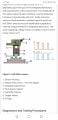
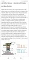
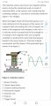
First of all ,Hi for everyone I am a new member here. So I have a little struggle with one car .... the car have a engine swap so the old engine have a hall effect sensor for the crankshaft ,and the new installed have a same engine but older model with the inductive crank sensor .. the molding on the engine not allowing installation for the new hall type sensor end magnetic ring . First its a vw diesel engine ,what we need to know the car have a edc16 Ecu , the old car have a edc15 + ecu end because the other components also using the Ecu like abs,agr,.... etc. I can not swap it . The first thing I'm thinking somehow to make a signal converter (for the teeth count ,I think some of my tuner frend can make adjustment in the MAP ,end I don't concentrate now on that just the converter ) what I know the hall sensor have a 3 pin connection one:+ power , one:- ground end a :signal output ,so I assuming it give out 0-5v square wave signal to ecu . The inductive have a power :+ , ground :- , end also a : signal out , I think its use 8v power input or 5v I need to look that info up . So I searching a converter schematics for this application if somebody can help. I thinking to use some kind a hall effect gear tooth sensor driver ic ,like in older types Bosch ecus they have directly connected inductive sensor to ecu ,inside they have a :Bosch 30221 driver, just I can not find any pinout or datasheet for this ic end I don't know have to build a signal converter using it (if it have a proper output ) end a second one I'm a car Mehanic not electro engineer ,but if somebody have a circuit I think I can built it . :D ,so one more time big thanks fin any kinda help.
 

drc_567

Joined Dec 29, 2008
1,156
... inductive crank sensor... Is it possible to give a more detailed description ... possibly a picture? Is there is a wire coil in place, such that a Hall Effect sensor could be positioned at one of the coil ends, so that it picks up the signal flux and produces a useable signal?
... or is something else involved?
 

Thread Starter

Dmitrij

Joined Feb 18, 2019
7
Hi , sorry I maded it a little bit confusing , so the inductive have a two wire end permanent magnet ,the ground is just for the coaxial cable outher couting to remove noise (its not having 5-8volt input .. my bad ) but I have taken a screenshots with better explanation ,I will attach it .
 

Attachments

drc_567

Joined Dec 29, 2008
1,156
.. going from square to sine wave is not too much trouble, a high frequency filter.
Going from sine to square is different. ... Here is one circuit, but there might be a better one someplace:
https://electronics.stackexchange.com/questions/163253/sine-wave-to-square-wave-schmitt-trigger.
... if you require the square wave amplitude to be 5 volts out, rather than the 3.3 volts in the example circuit, it seems like you would replace the 3.3 voltage source with a 5 volt source ... need to verify that particular detail.
... if you scroll down on the page link above, there are several sine to square circuits to look at ... can't say which would be best.

 
Last edited:

drc_567

Joined Dec 29, 2008
1,156
... for your consideration, it appears that there is a particular type of manufactured Hall Effect Sensor that is capable of sensing the motion of gear teeth, and producing the required square wave output signal.
The part number is:
55505-00-02-A-ND ... at Digi-key
Datasheet:
https://www.littelfuse.com/~/media/...e_hall_effect_sensors_55505_datasheet.pdf.pdf

If the details of the part are satisfactory, you would replace the original flux coil sensor with this one, and maintain your square wave output signal requirement. ... not absolutely certain what square wave amplitude is necessary, so take another look at that specification ... May require minor input voltage adjustment.

... there is a maximum of 2 mm clearance allowed between the gear teeth and the sensor, so keep that dimension in mind.
 
Last edited:

Alec_t

Joined Sep 17, 2013
15,111
Inductive sensors give an output amplitude which increases with speed and can reach tens of volts, so any adapter circuit needs to be able to handle that.
It's my understanding that at tickover rpm the ECU typically checks inductive sensor health by looking for an amplitude of about 5V peak, but for speed measurement is concerned with the intervals between peaks rather than their amplitude.
Here's a suggested adapter which emulates a Hall sensor output and accepts input signals in the range 1V to 100V peak. At the low end of the range (low rpm) the duty cycle is >>50% but tends towards 50% at the top end.
V+ is the Hall sensor supply voltage from the ECU. R2 is a pull-up resistor which may not be needed if there is already one in the ECU input port. You could check with an Ohmmeter if your Hall sensor has a built-in pull-up resistor.
Inductive-to-Hall-adapter.PNG
 

Thread Starter

Dmitrij

Joined Feb 18, 2019
7
Hi ,not bad I will try to build it ,but before I build I will try to reverse engineer the edc15+ Ecu (just the part which is related to the induction sensor, its 2 input pin 102 &110 ) so I think its need to have some sorte IC inside which converts the signal to square or digital , just the problem is the ic-s inside the ecu is bosch labeled so datasheet is not easy to find or possible.... but I have also looked for some sort a IC which can make this possible end I find :ACS714-30A , I think its perfect for this application its have 2 input terminals for the inductive sensor & on the other side its have power in, signal out ,gnd , if I understanding this correctly ,can you take a look ? I level in attached . Thank you .
 

Attachments

Thread Starter

Dmitrij

Joined Feb 18, 2019
7
For example putting the hall sensor in the bore of the inductor...or between it and the magnet
Hi, not because the inductive sensor is mounted on the side of the engine end its picking the signal from wheel inside of engine mounted on crankshaft (so its closed) but the new model have the hall sensor mounted under the flywheel end its picking signal from a magnetic ring what is pressed on the end of the crankshaft & its also a oil seal end the engine don't have place to mount the sensor because its a little bit difrent on the flywheel side different molding .
 

Thread Starter

Dmitrij

Joined Feb 18, 2019
7
Inductive sensors give an output amplitude which increases with speed and can reach tens of volts, so any adapter circuit needs to be able to handle that.
It's my understanding that at tickover rpm the ECU typically checks inductive sensor health by looking for an amplitude of about 5V peak, but for speed measurement is concerned with the intervals between peaks rather than their amplitude.
Here's a suggested adapter which emulates a Hall sensor output and accepts input signals in the range 1V to 100V peak. At the low end of the range (low rpm) the duty cycle is >>50% but tends towards 50% at the top end.
V+ is the Hall sensor supply voltage from the ECU. R2 is a pull-up resistor which may not be needed if there is already one in the ECU input port. You could check with an Ohmmeter if your Hall sensor has a built-in pull-up resistor.
View attachment 170568
Thanks , I will try this when I have time to work on the car, end report back .
 

Thread Starter

Dmitrij

Joined Feb 18, 2019
7
... for your consideration, it appears that there is a particular type of manufactured Hall Effect Sensor that is capable of sensing the motion of gear teeth, and producing the required square wave output signal.
The part number is:
55505-00-02-A-ND ... at Digi-key
Datasheet:
https://www.littelfuse.com/~/media/...e_hall_effect_sensors_55505_datasheet.pdf.pdf

If the details of the part are satisfactory, you would replace the original flux coil sensor with this one, and maintain your square wave output signal requirement. ... not absolutely certain what square wave amplitude is necessary, so take another look at that specification ... May require minor input voltage adjustment.

... there is a maximum of 2 mm clearance allowed between the gear teeth and the sensor, so keep that dimension in mind.
Its also a possibility ,I will try first with the circuit suggestions what I have here ,if nothing its also a great idea ,thanks.
 

Alec_t

Joined Sep 17, 2013
15,111
I find :ACS714-30A , I think its perfect for this application
I'm afraid I don't. According to the datasheet, the typical sensitivity for that IC is only 66mV/A. So, for a typical sensor coil resistance of ~1.5k and a ~5V sensor signal the input current to the IC would be ~3mA, giving an output of only ~200uV.:(
 
Last edited:

geekoftheweek

Joined Oct 6, 2013
1,429
If you just need to convert to square wave...

I've had pretty decent luck with https://datasheets.maximintegrated.com/en/ds/MAX9924-MAX9927.pdf connected to an old VR type distributor. They are however extremely small and I lost two before I even made the first circuit.

Another possibility is using a standard GM early 4 pin HEI module to create a square wave. They're built to withstand automotive environments from the beginning.
 

cork_ie

Joined Oct 8, 2011
428
Don't go any further with this project just yet.
From your initial post I assume what you have done is swapped a 1.9tdi engine in a Golf or Passat . You have replaced a more modern 1.9Tdi PD engine(BLS, BKC, BXE etc.) with an older engines with code AVB, AWX or AVF .
I will be very honest with you. These engines are very different and just changing the sensor will do absolutely nothing for you. In fact I know for certain that the later (EDC16) engines like BLS, BKC, BXE etc will start and run on either a cam or crank signal but will be hard to start and run at reduced power. Most of the peripherals are also different. The turbo is different, the EGR valve is different, the injectors are different etc etc. They are completely different generation engines. Even if you get the engine to run it will never be satisfactory.
I know there was an issue with the oil pump drive failing and the whole balance shaft setup in the later engines and there was a modification using the older engine block. That does not mean that you can transplant an engine from a previous generation and hope everything is going to work ; because it won't. To avoid lots of expense and disappointment , do some research before you proceed any further.
 
Top