Agreed. Measuring an AC signal with a meter set on DC will yield wildly fluctuating readings. That's why back some ways I suggested setting the meter to AC to see what we get. I was surprised when the readings came back the same. I'm wondering if the meter isn't set up right or if the TS is using it set to measure current.
I have a neighbor who used to regularly call me to come check his car battery. For Christmas I gave him his very own meter. One day he called me and said "the meter you gave me doesn't work". He blew out the fuse because he set it to read current then touched the battery terminals. I replaced the fuse and gave it back. Once again he blew the fuse in the same way.
His father and mine both come from an era where electricity was often referred to as current. I remember my dad speaking of that all the time. It's quite possible my neighbor thought of it the same way and figured if he wanted to read the battery he set it to current. Which as we know - setting the meter to read current then sending 12 VDC through a 300mA fuse is likely going to yield a blown fuse. Today I don't know if meters are better protected internally so as to avoid such a mistake. It's also possible the TS is setting the meter to read ohms, though he said he's taken readings with AC and DC settings. To be flatly honest, I haven't a clue how he's coming up with those voltages on an assumably working piezo circuit.
i think i am capableof using my meter and i have measured the voltages from the battery -ve to the +ve of the piezo and from the -ve of the battery to the -ve of the piezo -
answer to post 10.....
off no beeps on beeping
-ve battery to +of piezo 1.28v 1.21v
-ve battery to -ve of piezo 1.28v 1.21v
due to autamatic formating the 1.21v are both when the piezo is beeping and thus fluctuate
the whole idea was to trigger an scr from the piezzo beeping from which i could power seperately through the scr either an led or what might be more useful a relay, the scr will of cause latch on..............so the idea was to try to make a solid trigger from the piezo isgnal i thought using a darlington transistor to ggive a reliable trigger for the scr.
i thought i made this clear but obviously not.
Your idea is and has been perfectly clear at least in my mind from the beginning.
The problem is not being able to get sufficient data on the beeper.
Can you post some photos of the beeper and circuit board as requested earlier?
This might help and any chance you have access to an oscilloscope?
My apologies if I've offended you. Just that I have encountered enough people who make mistakes to make me ask the question. I, too, have set up test equipment incorrectly and gotten readings that didn't make sense. It happens. Really, no insult intended.
OK, in post #6 we find that it is a kitchen timer that is powered by a 1 1/2 volt battery.
THAT tells me that it is a simple piezo sounder disc driven by the timer circuitry. THAT took a while to discover. It also means that there is no power source that is part of the system that can trigger an SCR without some amplifying. So there will need to be an AC coupled amplifier and a separate power supply of some kind, because a single 1 1/2 volt battery is not enough. But that is not an issue because the SCR is already going to control some power more than the single battery. In addition, since there already needs to be an amplifier of some source, using a microphone will certainly provide isolation to avoid disrupting the timer circuit, AND it will be able to be tested easily .
i can read simple schematics, but would it be possible for someone to draw me a simple circuit to amplify the signal from a piezo buzzer beeping to trigger an scr and turn an led or relay on?
i will give that circuit a try but it may take me a few days to get back to you.
yes i think this is correct......... it is a simple piezo sounder disc driven by the timer circuitry. (post 26)
i will also try and get some pics of the board.
one thing i will say is that using 3v the piezo is louder,but the timer will not work, it works on dropping back to 1.5v AAA.
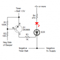
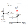
BINGO!! the circuit by sghioto (post 27) WORKS PERFECTLY !! THANK YOU !!!!!!
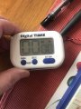
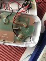
I attch some photos of the cheap timer....i think the peiezo has its own driver,it is not a just thin disc but in a thick black encloser, (TOP RIGHT OF PIC)
I added a switch between the 1k resistor and the gate of the scr so the beeps when setting the timer dont turn on the led/relay straight away , once timer set the switch can be turned on and the led / relay turns on at the end of the time. (i guess it could have been added on the power side of the scr as well)
ANYWAY IT WORKS !!! THANK YOU SO MUCH.

 Facebook
 Google
 GitHub
 Linkedin