Facebook
 Google
 GitHub
 Linkedin
Hi,
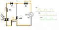
I'm designing the trigger circuit of the triac couplers without zero crossing

I use the MOC3023 that is powered by the mains voltage through the load, everything is fine as long as the load is stable.
The Resistor that limits the gate current RG depends on the load RL when the load changes I am forced to resize RG.
Can anyone tell me if there is a method to make the circuit independent of load variations?
The only possibility I found is to use a pulse transformer
I'm designing the trigger circuit of the triac couplers without zero crossing
I use the MOC3023 that is powered by the mains voltage through the load, everything is fine as long as the load is stable.
The Resistor that limits the gate current RG depends on the load RL when the load changes I am forced to resize RG.
Can anyone tell me if there is a method to make the circuit independent of load variations?
The only possibility I found is to use a pulse transformer