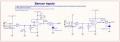
circuit to test if mosfets are on or off. Does it look sane?

#12

Joined Nov 30, 2010
18,224
There was a long conversation between me and Scott, but I don't believe anything is wrong with your op-amp configuration. I and ronv think we were having a language difficulty.

Now that ronv mentioned input range, I can ask, what range are your inputs going to be?

You can lower the 1 meg resistors to 100 k for a maximum error of 0.05 volts, or 10 k to arrive at 0.007 volts (maximum) error in input offset voltage.

You can tell me what voltage range you need these buffers to work in and I can say if you need a different amplifier. ps, the LM358 works very well with a 12 volt supply. You might do that and fix the idea that the sensors will input higher than 1.8 volts. Then you would add a clamp like you did on the external peripherals block.

ps, just lucky I couldn't sleep. It's nearly 5 am here and I got up 1 minute after you posted. :p
 
Last edited:

#12

Joined Nov 30, 2010
18,224
The 609 has an input range of 1.1 volt less than the power supply. That would be 2.1 volts maximum. The 358 has an input range of power supply minus 1.5 volts for a maximum of 1.8 volts from the sensor.

Not much better.

What is your REAL voltage input?
 

Attachments

ScottWang

Joined Aug 23, 2012
7,504
There was a long conversation between me and Scott, but I don't believe anything is wrong with your op-amp configuration. I and ronv think we were having a language difficulty.
Sorry about that, but not the language problem, is the conception and angle.

Now that ronv mentioned input range, I can ask, what range are your inputs going to be?

You can lower the 1 meg resistors to 100 k for a maximum error of 0.05 volts, or 10 k to arrive at 0.007 volts (maximum) error in input offset voltage.
See my first post in #4:
If the power is not providing from battery, maybe the input resistors of mosfet and op amp could be reduce some more.
 

#12

Joined Nov 30, 2010
18,224
If the power is not providing from battery, maybe the input resistors of mosfet and op amp could be reduce some more.
True. These could be much lower resistance to provide better speed and leakage control.

I still struggle with your language. I must slow down to understand you.
 

Thread Starter

Toebs

Joined Oct 9, 2014
55
The 609 has an input range of 1.1 volt less than the power supply. That would be 2.1 volts maximum. The 358 has an input range of power supply minus 1.5 volts for a maximum of 1.8 volts from the sensor.

Not much better.

What is your REAL voltage input?
Hi I did not receive email notification and I have first noticed the "second page" of the thread just now, hence the slow response on my part :)

the moisture sensor is a VH400 from Vegetronix. it can be powered with 3.5V-20V but always outputs 0-3.0V according to moisture content in the soil. The 0-3V represents 0-70% VWC (volumetric water content). The VH400 is specified to have an accuracy of 2%, so i would like my circuit to not mess this up to badly. So maybe 100k resistor?

I have some questions in regards to the MCP609 since I am currently using these on another board, also measuring with the VH400.
You say that the 609 has an input of 1.1v less than its power supply, but i thought it was rail to rail, and that this meant there would be no such issue, but I guess im wrong, but this leads me to the question, where do you read this spec?

Also on this other board I supply both sensor and the 609 with 5V and i am using the same 1Meg resistor configuration. So given that i have a 0-3V input i am in the clear in regards to the 1.1v less. The MCP609 has really low bias current 80pA, so the error would be really low, right? Or do i also have a problem in this design?
 

#12

Joined Nov 30, 2010
18,224
The limiting input voltage is called Common Mode Input range.
Your input resistor on this voltage follower depends on whether the input signal has a low enough resistance to allow the Input Bias Current to flow without developing much error voltage. You might not need an input resistor at all! The penalty would be that the op-amp output will latch high when the sensor is unplugged.

"Rail to Rail" an apply to inputs and outputs. That is where you missed a point.

Still, at 80 pa, a 1 meg resistor will only develop 60 uv in the worst case scenario.
Be aware that I am guiding you in designing for worst case conditions.
Your real response will be better than what I am describing, almost all the time.
 

Thread Starter

Toebs

Joined Oct 9, 2014
55
OOk im back :).

Ok that is good stuff to know about how opAmps works! I am really positively amazed about this forum and all the awesome feedback I get :)
It's nice to be guided in worst case conditions, wouldnt want it any other way ;).

I have done some updated to the opAmp circuit based on what was suggested and a few more.

- I changed resisters from 1M Ohm to 1kOhm
- I put clamps on the opAmp outputs
- I put a bypass capacitor on the opAmp power supply
- I added a low-pass filter from the sensor inputs to opAmp (Fc ~ 30Hz). The VH400 does some high frequency stuff, dont want it to be upsetting things :)

I have attached a picture
 

Attachments

ScottWang

Joined Aug 23, 2012
7,504
The R300 and R301, R303 and R304 will became the voltage divider, it will caused the output of LM358 very small, it that enough for your ADC?
 

Thread Starter

Toebs

Joined Oct 9, 2014
55
The R300 and R301, R303 and R304 will became the voltage divider, it will caused the output of LM358 very small, it that enough for your ADC?
Hmm you are right. That is not good. Maybe I should just leave out the LP filter, or can I fix it somehow?
 

Thread Starter

Toebs

Joined Oct 9, 2014
55
The sensor has an output impedance of 10K ohms, so I would stick with a large resistor.
If i change it to large value, I will get the voltage offset from the bias current, so maybe I need another opAmp instead which can handle up to 12V and has a low bias current i guess?

[edit] Well ok i guess the "typical" bias input current is 20nA, so unless im pretty unlucky I will not have to much trouble using a large resistor
 
Last edited:

#12

Joined Nov 30, 2010
18,224
You can use, "typical" if you're not going to make a 100,000 production run of these.
When you make thousands of them, you're going to find the bad ones.
 

Thread Starter

Toebs

Joined Oct 9, 2014
55
Ok cool. I have shipped my gerbers to itead studio.
Just a question in relation to the LP filter, which I might add later if it proves to be necessary. If i keep the 1M resistor (R300) and use a larger cap (C301) in the LP and hence a smaller R301 I will not really have the voltage divider issue proposed by scott wang. Right? :)
 

ScottWang

Joined Aug 23, 2012
7,504
You have to measure the voltage of zener diode first, because its voltage range are 3.14 3.47V, so it could be over 3.3V.
If you want to using a voltage divider on the input of op amp then you have to calculate the input voltage of moist and adc.
 
Top