Circuit to control the resistance of an exercise bike.

Thread Starter

Xavier Pacheco Paulino

Joined Oct 21, 2015
728
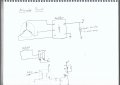
I have an old exercise bike which doesn't have the driver board. It only has an alternator and 2 big power resistors (load). I expect to build a simple controller to save the bike. I attach a circuit that I made in which I think to control the field voltage by using PWM from Arduino (let's say). I can, for example, use a potentiometer to gradually vary the resistance of the bike. Do you think the circuit could work? What improvements can be made? I look for a cheap solution since it's an old bike.

Note: The rectifier is inside the alternator, so the alternator outputs a DC voltage.
 

Attachments

Last edited:

crutschow

Joined Mar 14, 2008
34,465
You could also use a 555 astable timer circuit to generate the PWM signal such as below.
The 100kΩ pot U2 adjusts the PWM duty-cycle.
The LTspice simulation shows the waveform duty-cycle for pot settings of 20% and 80%.
The value of C2 gives a PWM frequency of ≈1kHz. You can change its value if you want a different frequency.

This circuit can drive the MOSFET directly.
You shouldn't need the opto isolator.

upload_2018-5-16_10-53-2.png
 

MaxHeadRoom

Joined Jul 18, 2013
28,699
I have done it with a simple LM311 comparitor and a pot to regulate the field.
One input the pot, the other the voltage output value.
Max.
 

Thread Starter

Xavier Pacheco Paulino

Joined Oct 21, 2015
728
You could also use a 555 astable timer circuit to generate the PWM signal such as below.
The 100kΩ pot U2 adjusts the PWM duty-cycle.
The LTspice simulation shows the waveform duty-cycle for pot settings of 20% and 80%.
The value of C2 gives a PWM frequency of ≈1kHz. You can change its value if you want a different frequency.

This circuit can drive the MOSFET directly.
You shouldn't need the opto isolator.

View attachment 152619
I'm comparing your circuit with others around the web. I've seen some variations which I attach in this post. What does really make the difference in the operation of the PWM?
 

Attachments

crutschow

Joined Mar 14, 2008
34,465
I've seen some variations which I attach in this post. What does really make the difference in the operation of the PWM?
The first shares the output of the 555 between the PWM feedback and the load, which saves a resistor.
That also makes the PWM duty-cycle directly proportional to the pot position.
My circuit leaves the output free to drive the load, but the duty-cycle is slightly offset from the pot position (i.e., a 50% pot position is not quite a 50% duty-cycle) due to the presence of the added R1 resistor.

The second circuit is the same as my circuit except that the pot is on the other side of the diodes.
The circuit operation is exactly the same.
 

Thread Starter

Xavier Pacheco Paulino

Joined Oct 21, 2015
728
The first shares the output of the 555 between the PWM feedback and the load, which saves a resistor.
That also makes the PWM duty-cycle directly proportional to the pot position.
My circuit leaves the output free to drive the load, but the duty-cycle is slightly offset from the pot position (i.e., a 50% pot position is not quite a 50% duty-cycle) due to the presence of the added R1 resistor.

The second circuit is the same as my circuit except that the pot is on the other side of the diodes.
The circuit operation is exactly the same.
Got it. Thank you.

One last question: in my first post where I attached the circuit with the alternator, is the big load resistor well connected? Is its purpose just to dissipate heat?
 

Thread Starter

Xavier Pacheco Paulino

Joined Oct 21, 2015
728
It's connected properly.
Yes, its purpose is to dissipate all your exercise energy (fat calories ;)) converted to heat.
What if I don't put the resistor? I mean, what can occur if the exercise energy didn't have a path to go?
Also, in the PWM circuit, should I feed the transistor with the alternator voltage or with the 555 supply voltage? Because I plan to use a separate 12V power supply to feed the 555 circuit. The DC voltage from alternator is kind of unstable.
 

crutschow

Joined Mar 14, 2008
34,465
What if I don't put the resistor?
Then the generator will provide no extra pedal resistance since it is outputting no power.
The generator needs a load to get rid the energy of your pedalling.
in the PWM circuit, should I feed the transistor with the alternator voltage or with the 555 supply voltage?
I assume you mean the field coil voltage.
Depends.
The alternator pedal resistance will be relatively constant with speed with a fixed supply voltage to the field coil.
Connecting it to the output voltage with tend to make the resistance more proportional to the pedal speed.
 

Thread Starter

Xavier Pacheco Paulino

Joined Oct 21, 2015
728
Then the generator will provide no extra pedal resistance since it is outputting no power.
The generator needs a load to get rid the energy of your pedalling.
I assume you mean the field coil voltage.
Depends.
The alternator pedal resistance will be relatively constant with speed with a fixed supply voltage to the field coil.
Connecting it to the output voltage with tend to make the resistance more proportional to the pedal speed.
So, this is what I have in mind:
12V separate supply for the 555.
Alternator output voltage to load resistance and field coil voltage. As you say, the generator needs a load to get rid the energy of the pedalling, so my loads will be the power resistor and the field coil.
 

Tonyr1084

Joined Sep 24, 2015
7,905
How about this:

12 volt supply feeds the PWM and feeds the armature winding (the single coil).
The output of the alternator is connected to a load resistor of sufficient wattage. That way pedal harder get more resistance. Pedal lighter get less resistance. RPM makes the difference at the load. Higher RPM will output more energy, therefore it will be harder to pedal faster. Kind of self regulating. If you want a less challenging ride you can lower the input voltage to the armature. More challenging, more voltage.
 
Top