Circuit Needed for Unlocking Power Supply Safety Mechanism

Thread Starter

SnowCrash

Joined Apr 6, 2016
31
So, perhaps something like this?
like it but I think I'd add a lot more resistance to R2 (and then R4), so that:
1) the cap C1 could be smaller and cheaper, and
2) the initial resistive load seen by the Magsafe is more dependent on R1 and very little changed by whether R2 is conducting or not. As drawn, the initial load would be R2 in parallel with R1 and this would be a lot less than 39K.
Good point. Thanks. I'd overlooked R2 being effectively in parallel with R1 while the cap charges.
Thank you very much Alec_t & wayneh!

I've tried looking into formulas for calculating RC circuits but the subject seems extremely complicated and most people seem to think the best course is to just try out different values and see what works. However, as this is new territory for me, I'm not even sure where to start (I guess one just develops a 'feel for it' after a while, but I'm not there yet).

From the above-quoted comments, I take it Alec_t's original values are not optimal for this application. I was therefore hoping you guys could point me in the right direction in terms of reasonable values for:
R2 - ?
R4 - ?
C1 - ?
(I'll happily play around with different values when testing, but a starting-point would be very much appreciated)

Also, does 'Rload' in Alec_t's latest diagram represent an actual 30R resistor to be included in the circuit or is it just a conventional way of marking where the rest of the circuit will go?

You would need to tweak R2, depending on the gate threshold voltage of the FET.
Lastly, would it make sense to replace R2 with a fixed resistor and a trimpot in series so as to allow a wide range of FETs to be used regardless of their precise gate threshold voltage. And if that makes sense, what value would you use for the trimpot?

Thanks again,
SnowCrash
 

Alec_t

Joined Sep 17, 2013
15,147
Try C1=10uF, R2=250k trimmer with 100k in series, R3= 1meg. Rload just designates the rest of the circuit; not an additional resistor. The FET is not critical: it just needs to handle the expected load current and voltage.

Edit:
If the FET doesn't switch off quickly enough when the Magsafe is disconnected you could reduce R4 to, say, 680k.

Edit 2: Ignore the above edit.
 
Last edited:

wayneh

Joined Sep 9, 2010
18,133
Try C1=10uF, R2=250k trimmer with 100k in series...
If you don't have a pot to play with, you can just experiment with fixed values. You'll probably want that for the final solution anyway.

If you want to play with the math, start with the threshold voltage of the MOSFET you choose. The load will be shut off below that threshold and will begin passing current as the gate voltage rises above it. The fan will not begin turning until the voltage is well above the threshold. I have no idea what "well above" means but suppose it's 1V.

The capacitor will be at 0V when it starts to charge up. The voltage on the capacitor will look like: Vcap = Vmax•[1-exp^(-RC/t)].
You can think of it as an exponential decay of the difference between Vmax and Vcap. These curves all look the same, only the units are different. Time t in seconds can be expressed in units of RC. The passage of each RC time constant will shave of 63% of the ∆V remaining at the start of that period. So if ∆V starts at Vmax = 20V, it will be only 7.4V (meaning Vcap = 12.6) after RC seconds.

A MOSFET would be fully turned on at a gate voltage that high. So your fan might come on in as little as ~1/2RC seconds. So choose RC combination of ~2 seconds as a back-of-the-napkin starting place. 2µF and 1MΩ, or 10µF and 200KΩ and so on.
 

Alec_t

Joined Sep 17, 2013
15,147
It's occurred to me that the Magsafe may not be designed to handle inductive loads such as a fan and it would therefore be advisable to add some back-emf protection components to the circuit.
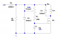
Here's the latest mod to the circuit. The diodes are rated at 1A, assuming the fan current is less than that.
MagTrigger4.PNG
 

Thread Starter

SnowCrash

Joined Apr 6, 2016
31
Try C1=10uF, R2=250k trimmer with 100k in series, R3= 1meg. Rload just designates the rest of the circuit; not an additional resistor. The FET is not critical: it just needs to handle the expected load current and voltage.
If you don't have a pot to play with, you can just experiment with fixed values. You'll probably want that for the final solution anyway. If you want to play with the math... and so on.
It's occurred to me that the Magsafe may not be designed to handle inductive loads such as a fan and it would therefore be advisable to add some back-emf protection components to the circuit.
Here's the latest mod to the circuit. The diodes are rated at 1A, assuming the fan current is less than that.
View attachment 129121
Thank you very much Alec_t for the circuit diagrams & info! and thank you very much wayneh for the input and in-depth explanation!

Also, my apologies for the delay in reporting back - my laptop broke down completely over the weekend :-@

Nevertheless... I think we have a winner :)

I've built the circuit according to Alec_t's latest diagram and so far it's been working flawlessly! 1 sec delay and the fan turns on like clockwork! Very cool indeed :)

I'd like to run a few more tests before making the final post with a complete schematic and relevant info for anyone who might be interested in this in the future (e.g. I want to see if the 39K4 value is critical or if there's a range to work with there, as well as build the entire circuit I want to use in my project as the fan is just a part of it), but I wanted to post this update as soon as I could.

Once I run the additional tests and get my laptop back from repair I'll post again.

In the meantime, thanks a million, guys!
SnowCrash
 
Top