Circuit Help: I need a regulated PS with shutdown

Thread Starter

raddybaby

Joined Jun 22, 2009
3
Hi,

I am building a simple datalogger and need

1. to wake up the Pic with a single momentary switch
2. to use minimial power in sleep mode
3. to use a 6V battery
4. to power the Pic with 3.3V

My thought was to use the mom switch to provide mom voltage to the shutdown pin of a LDO 3.3V regulator - this would provide power to the Pic...the first thing the pic would do would be to keep the shutdown pin high.

The LDO regualtor I am considering is the TC2054 and the enable needs to be 60% of the Vin so I think I'll have issues.

I am guessing this a common problem so are there any standard solutions out there?

Many thanks and cheers,
Neal
 

eblc1388

Joined Nov 28, 2008
1,542
The LDO regualtor I am considering is the TC2054 and the enable needs to be 60% of the Vin so I think I'll have issues.

I am guessing this a common problem so are there any standard solutions out there?
You are correct about the 60% Vin or higher /SHUTDOWN pin level requirement. This would translate to 3.6V or more which the output of the regulator or PIC cannot provide normally.

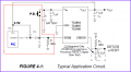
This is my suggestion. I have no idea it would work or not. Basically, the PIC CLKOUT output is used to provide DC 5V from 3.3V supply, which is what the shutdown pin needs.

The PIC can also turn itself off by executing a SLEEP instruction.


Attachments

John Luciani

Joined Apr 3, 2007
475
Why not put a pullup resstor on the /SHUTDOWN and use the
momentary switch to pull the /SHUTDOWN low?

The LDO is always on. The momentary switch briefly shuts down
the LDO and the PIC resets when the LDO restarts.

(* jcl *)
 

THE_RB

Joined Feb 11, 2008
5,438
Just use a better low drop out regulator. The last one I used for this type of 3.3v app had a quiescent current of 10 to 12 uA. Farnell has them in the catalogue, under $2, they are a SMD part but you can use them with a little patient soldering.

Then just put the PIC in sleep mode?
 

Thread Starter

raddybaby

Joined Jun 22, 2009
3
Thanks all!

1. L Chung - I think the circuit posted is clever ;-)

2. John, that would definitely work! but when "shutdown" the LDO is very low current draw (about 0.5uA) when not shutdown the draw is much higher (about 55uA)....not terrible but not good enough for my application/battery....it would drain the battery in 3 months or so.

3. the RB - My choice of components is influenced by what is being used by existing products - but not set in stone...a draw of 10uA would drain the battery in 15-18months...maybe OK but I'd like to do better.

Taking RB's advice I've looked around a bit more and the TC1054 LDO regulator that SD voltage min is 45% of VIN (rather then 60% for the TC2054 I was hoping to use)...I will also add 1 perhaps 2 diodes in series between the battery and the LDO to lower VIN to provide plenty of margin.

I will post the final setup once it's built and tested.

Once again for your help!

Cheers,
Neal
 

John Luciani

Joined Apr 3, 2007
475
2. John, that would definitely work! but when "shutdown" the LDO is very low current draw (about 0.5uA) when not shutdown the draw is much higher (about 55uA)....not terrible but not good enough for my application/battery....it would drain the battery in 3 months or so.
You can shutdown the LDO using transistors. More parts put would save you
the current. I would use BJTs (3904 and 3906). The BJT turns on at 0.7V and can support output voltages to 40V which gets you to your Vin level.

(* jcl *)
 

Thread Starter

raddybaby

Joined Jun 22, 2009
3
Hi John,

Thanks again! That is likely the way I'll go about it.

As for the circuit posted above....I think it would be best to tie the second input to the shutdown to an outpu pin of the PIC then to the 3.3V output...just to be sure the pic can power down the LDO.

Cheers All,
Neal
 

John Luciani

Joined Apr 3, 2007
475
Hopefully I didn't misunderstand the problem. You want a circuit where the (1) the PIC
could enable the LDO or (2) the switch could. The circuit below will "OR" together multiple
lines to force the enable pin to the battery voltage.

(* jcl *)
 

Attachments

Top