 Facebook
 Google
 GitHub
 Linkedin
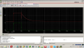
What do you think about this circuit? I simulated the analog part in Orcad, but I get the voltage over the coil to always be 5V, when I give "1" it becomes 12V.
Attachments
-
 154.7 KB Views: 14
 -
 443.4 KB Views: 12
 -
 403.1 KB Views: 12


