Facebook
 Google
 GitHub
 Linkedin
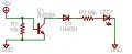
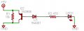
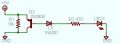
I need some electronics 101 help understanding how this circuit works (see attached). I can't seem to get my mind around what is happening so I can do the math for the entire circuit. 
My explanation is that when power is applied, the transistor is biased high, sending a current out of the base to the diode, resistor & LED. But my mind wants to say this is what should happen with an NPN because it's in an Emitter-Base arrangement - but the circuit doesn't work with an NPN.
As an aside, I also don't understand the pulldown 10k resistor - why is it connected to ground & just not in series with the emitter? Guess I don't quite get the "pulldown/pullup" concepts either, lol. But for now I just want to understand why this PNP circuit works.
As always, appreciate any help & thanks for your time.
Attachments
-
 2.4 KB Views: 68
 -
 13.7 KB Views: 57