Circuit distorting AC signal from CT

Thread Starter

Blue_Electronx

Joined Jun 10, 2019
112
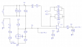
Picture 1 shows a 60Hz signal from a CT only with the burden resistor connected. Picture 2 shows the signal when I connect it to the opamp circuit. Picture 3 shows the op amp circuit. Some points on it:
x1,x2 - z1-z2 are analog switches: SN74LVC2G66DCUR
L1 L2 are two identical secondaries (same turn ratio) from the same CT. One is used for primary sensing and the other is occasionally used for testing.
D12 sets the DC offset to Vcc/2

My guess is that the culprit here is related to the analog switch. Any light on this?
 

Attachments

Papabravo

Joined Feb 24, 2006
22,082
That analog circuit is a hot mess. What is it trying to do?
Is the non-inverting (+) input supposed to be a reference? Why is it connected to 2 different sources?
Why are you using a single supply opamp with an AC circuit?
 

Thread Starter

Blue_Electronx

Joined Jun 10, 2019
112
That analog circuit is a hot mess. What is it trying to do?
Is the non-inverting (+) input supposed to be a reference? Why is it connected to 2 different sources?
Why are you using a single supply opamp with an AC circuit?
I'm applying the concept explained in the app note attached:
AC Coupled, Single-Supply, Inverting and Non-inverting
Amplifier
 

Attachments

Papabravo

Joined Feb 24, 2006
22,082
That's funny, I don't see much in the way of similarity. You seem to have way more components than the guys who wrote the application note. They were not dealing with inductors and transformers either. So wasup!

Edit:
What opamp are you using?
What is the transformer primary connected to?
What is the turns ratio from primary to secondary?
 
Last edited:

Thread Starter

Blue_Electronx

Joined Jun 10, 2019
112
That's funny, I don't see much in the way of similarity. You seem to have way more components than the guys who wrote the application note. They were not dealing with inductors and transformers either. So wasup!

Edit:
What opamp are you using?
What is the transformer primary connected to?
What is the turns ratio from primary to secondary?
You're right in that my circuit looks more complex. But they both can deal with AC signals. I don't need dual power supply. It's very common nowadays to use single supply with AC signals just adding a DC shift so the ADC don't see negative voltages. Regarding your questions:
1- I'm using opamp OPA317.
2- It's a CT so it's a single turn primary where the current you want to measure flows through it.
3- The transformer has 1000 turns in the secondary and test windings
 

Papabravo

Joined Feb 24, 2006
22,082
Now I know I am going soft in the head.
Here is what you need for the ADC

CT Current Measurement.png CT Current Measurement_PLT.png

Get rid of R22 and C32. A single stage RC filter after the opamp with a 100 KHz. corner frequency is as useless as a screen door in a submarinie
Get rid of that other feedback network of R28 and C18. That isn't helping either, especially if you connect the jumper
Your shunt regulator for the 1.33 volt reference is OK
I'm not sure what the other stuff is about
I think the winding that you are sensing needs one end grounded
Other than that I think this circuit was thrown together rather than designed and the presence of a wiring error cannot be discounted
Other than that it just might wight work
 

Attachments

Last edited:

Thread Starter

Blue_Electronx

Joined Jun 10, 2019
112
Now I know I am going soft in the head.
Here is what you need for the ADC

View attachment 215732 View attachment 215735

Get rid of R22 and C32. A single stage RC filter after the opamp with a 100 KHz. corner frequency is as useless as a screen door in a submarinie
Get rid of that other feedback network of R28 and C18. That isn't helping either, especially if you connect the jumper
Your shunt regulator for the 1.33 volt reference is OK
I'm not sure what the other stuff is about
I think the winding that you are sensing needs one end grounded
Other than that I think this circuit was thrown together rather than designed and the presence of a wiring error cannot be discounted
Other than that it just might wight work
Thanks. The idea of having R28 and C18 is it makes the amplifier close to unity gain when x1 x2 points close. In general the idea was to have switchable gains, i.e., 62 when x1-x2 is open, and unity when x1-x2 is closed.
 

Papabravo

Joined Feb 24, 2006
22,082
Thanks. The idea of having R28 and C18 is it makes the amplifier close to unity gain when x1 x2 points close. In general the idea was to have switchable gains, i.e., 62 when x1-x2 is open, and unity when x1-x2 is closed.
So the circuit is having problems and you're adding complexity instead of locating the problem. Good strategy.
 

Ian0

Joined Aug 7, 2020
13,131
I have a different strategy. I seriously underestimated a CT's ability to destroy any circuitry connected to it when there is a large current surge through it (big toroid being switched on)
Reduce the burden resistor. I used 0.05 ohm (for a 1A output CT). Then amplify with an AD8418. The AD8418 has the ability to centre the output at half-supply without any external components. It may not be as cheap as an op-amp, but it will withstand -4V to +70V on the input, and needs no gain-setting resistors.
It takes an awful lot of current through a CT to produce 4V across a 0.05 ohm burden resistor!
The only extra components I added were a couple of 1k resistors to give the inputs some DC level.
 

MisterBill2

Joined Jan 23, 2018
27,507
The output circuit could also be protected using a series resistor to limit the current and shunt diodes to clamp the voltage. If the maximum normal voltage out is less than a volt then 2 diodes in series will be adequate and not start conducting until over a volt. And the 100 ohm current limiting resistor will not drop much voltage until the diodes start conducting. You would need a second set of 2 diodes connected in the reverse direction, in parallel with the first set, for complete protection.
The benefit of this arrangement is that less gain is required and less gain leads to less noise.
 

Ian0

Joined Aug 7, 2020
13,131
True - the noise is lower. 110nV/rtHz from the AD8418. Gain =20. Bandwidth 723Hz. Total noise = 59uV
OPA317 noise = 55nV/rtHz. Gain =1 or 6 (use 1 for best case). Bandwitdh = 723Hz. Total noise = 1.5uV.
Connects to an A/D, lets say it is 12 bit on a 3.3V supply. 805uV per step. How will the noise affect it?
 
Could it be that you've swapped R33 & R35? What voltage did you intend your VREF to be? Why are not not just dividing the 3.3V to about 1.65V. Take care that all chopper op-amps behave weird whenever their inputs exceed the common mode range, which for a rail-rail input type has to be within 100mV-300mV of the rails. If you can't keep a chopper in the linear mode 100% of the time (for example during output clipping), it will need some recovery time before it can achieve zero offset. Since you bias the CT output to the Vref, I'm unclear why you also use a dc blocking capacitor? What is your D11 and can it really clamp the CT output to not exceed the 0-3.3V rails? For the high gain mode, you are not clamping you CT output enough to prevent clipping. The clamp should be across the feedback resistor, not the CT output.
 

ronsimpson

Joined Oct 7, 2019
4,690
First question: Something is wrong here. Maybe R33 is 10k not 30k. What voltage do you want?
1598675113550.png
Question: Why put a cap across a CT? L1 and C19 will make a LC resonant circuit. What is the part number of the CT? or did you make it?
1598675256869.png
OP-amp (-) pin4 is a ac ground. There should be no signal at pin 4. This puts the CT voltage across R27. This makes current flow from the output of the amp through R28 1k. I think this current must also flow in/out of D12 circuit. (if it even works) The point is that R27 is 1k load and R31 is 3.3k so I question of the "ref voltage" at TP9 has enough power to fight this load.
1598675436069.png
Why not put a 10uF cap from TP9 to ground?
What is the range the ADC can measure? 0 to 3.3V?
 

Ian0

Joined Aug 7, 2020
13,131
If you only need a gain of 1, then why do you need an op-amp?
The reference may also be problematic - the reference is accurate (probably better than 1%) but is the supply? If it's a 7833 then it's +/- 5%. That means there will be an offset on the signal. If the supply is not particularly regulated, the offset will vary with the supply.
It is therefore better to obtain the reference from a potential divider - that means it tracks the supply and stays in the middle.
Choose R so it will limit the current in case of an overload and the MCU protection diodes will clamp the over-voltage (or add a couple of schottky diodes for extra protection)
C may needed depending on your sampling frequency to prevent any out-of-band interference signals causing aliasing. True, it will resonate with the LEAKAGE inductance of the CT, but it is damped by the burden resistor so the Q will probably be quite low.
And if more gain is needed, increase the burden resistor.
I have used this circuit, but I prefer the AD8418 circuit because I can swap the inputs from CT to current shunt as necessary.
 

Attachments

Last edited:

ronsimpson

Joined Oct 7, 2019
4,690
C may needed depending on your sampling frequency to prevent any out-of-band interference signals causing aliasing. True, it will resonate with the LEAKAGE inductance of the CT, but it is damped by the burden resistor so the Q will probably be quite low.
At high frequencies the internal C of the CT causes a resonant frequency ring. Adding more C only lowers this frequency. Use a RC filter if you want to remove the high frequencies. Make the R 10X the burden resistor to dampen the added C effect.
And if more gain is needed, increase the burden resistor.
Increasing the burden resistor changes the low frequency response. A 10X increase in burden resistor will move the 30hz role off to 300hz.
 

Ian0

Joined Aug 7, 2020
13,131
At high frequencies the internal C of the CT causes a resonant frequency ring. Adding more C only lowers this frequency. Use a RC filter if you want to remove the high frequencies. Make the R 10X the burden resistor to dampen the added C effect.
If you look carefully at my circuit, you will see it is a RC filter. R is the parallel combination of the bias resistors and C is across the microprocessor input. R is effectively in series with C, so C is not directly across the CT.
There is an LC filter, but the Q is very low because of the series R.
Putting capacitors across the burden resistors just requires rather large capacitors. I am generally using 1A output CTs with 1 ohm burden resistors so a parallel C would be ridiculously large.
Increasing the burden resistor changes the low frequency response. A 10X increase in burden resistor will move the 30hz role off to 300hz.
R = 2.pi.f.L, so f = R/(2.pi.L)
L is the leakage inductance, so it is a lowpass filter, (series L parallel R) so increasing f is not a problem.
Saturation would be the biggest problem if the output voltage gets too large, and accuracy will fall off if the magnetising current becomes too large a part of the output current, but there is latitude for a reasonable amount of variation in burden (probably not 10x). I'm not sure just how much variation the orginal post required.
 

ronsimpson

Joined Oct 7, 2019
4,690
If you look carefully at my circuit, you will see it is a RC filter.
RC low pass filter where the C does not effect the resonant frequency of the CT. The C does not carry 'current' and does not need to have low ESR.
1598723797456.png
L is the leakage inductance, so it is a lowpass filter, (series L parallel R) so increasing f is not a problem.
I just went to the lab and scanned one of CoilCraft's CTs. The leakage inductance has nothing to do with low end frequency response. With no primary and no LL, just using the secondary, the 100mH shorts out the resistors at low frequencies. (in this case there is 1 ohm of wire and 100 ohms of burden resistance) 100mH & 101 ohms makes the low end roll off.
1598726037517.png
I used 10 ohm, 100 ohm and 1k for the test. Burden resistor effects low end response.
The high end roll off is a function of C1 and R and has a ring at resonant frequency.
 

Ian0

Joined Aug 7, 2020
13,131
You should to look more carefully at my circuit. There already is R in series with C.
I'll have a look at a CT tomorrow - I'm not going out to the shed now because it's dark and raining like anything.
 
Last edited:

yevgeny

Joined May 20, 2017
15
Hello.

The circuit seems too flexible, but should work. I have no idea what offset you want (usually it is 1/2 of power supply), just calculate ratio for R33 & R35.
You don't need C17 - better install that capacitor between TP9 & GND.
If you want to see real signal from CT, you need floating scope connected between TP9 & TP7.
Your circuit represent inverting amplifier with virtual ground.

Thanks.
Yevgeny.
 
Last edited:
Top