Circuit design of a photodiode

ericgibbs

Joined Jan 29, 2010
21,531
hi p,
The pulse you posted looks as a voltaic measurement.?
[Was the same method used for both pulse measurements.?]

For faster operation as others have also stated is the photo conductive mode.

At approx 900nm thats a IR detector PD, asking the same question as post #22

E
 

Thread Starter

pooya_b

Joined Feb 25, 2021
59
That's a high output without an amp. What is the source of the IR light pulse?
Is the amplitude output from the photodiode important or due you just need a clean square wave output?
Amplitude is not very important to me in the first stage, I need more that the wave is displayed with high accuracy.
I am more interested in measuring the pulse length.
 

Thread Starter

pooya_b

Joined Feb 25, 2021
59
hi p,
The pulse you posted looks as a voltaic measurement.?
[Was the same method used for both pulse measurements.?]

For faster operation as others have also stated is the photo conductive mode.

At approx 900nm thats a IR detector PD, asking the same question as post #22

E
True, this photodiode is more suitable for IR, but I use it for 532 nm, which contains information inside the photodiode for 535 nm.
 

Thread Starter

pooya_b

Joined Feb 25, 2021
59
? Can you elaborate on that statement?
Is the light source a green laser?
My light source is a green LED.
This source produces pulses of nanoseconds to microseconds.
When the LED goes out, a phosphorescent material starts to radiate. I need a photodiode that can measure the time out of this material correctly.
But a photodiode without any circuit has a lot of fall time and it is not possible to observe the extinction time of the phosphorescent material.
 

Thread Starter

pooya_b

Joined Feb 25, 2021
59
Hello,

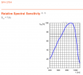
The sensitivity for 532 nm is only about half of the maximum sensitivity of the SFH2704:
View attachment 232651
Bertus
Yes that's right.
The thorlabs photodiode has about the same feature but works well.
I'm looking for something other than an amplifier in this photodiode that can show the exact time of blackout, but a photodiode without a circuit has a long blackout time.
 

ericgibbs

Joined Jan 29, 2010
21,531
hi pooya,
One method i have used in Laser and Echo sounder projects is generate a short/fast clamping/ suppression pulse on the falling edge of the main pulse.
In effect an active pull down on main pulse falling edge.

E
 

Thread Starter

pooya_b

Joined Feb 25, 2021
59
hi pooya,
One method i have used in Laser and Echo sounder projects is generate a short/fast clamping/ suppression pulse on the falling edge of the main pulse.
In effect an active pull down on main pulse falling edge.

E
hi ericgibbs
Explain more if possible. I also need fast clamping to be able to detect the real time the phosphorescence is turned off.
My measurement is mostly on pulse time.
 

ericgibbs

Joined Jan 29, 2010
21,531
hi pooya,
Please post the circuit that you used to drive the SFH PD as shown in post #1.

I will then will suggest a way of modifying the PD signal output.

E
 

Thread Starter

pooya_b

Joined Feb 25, 2021
59
hi pooya,
Please post the circuit that you used to drive the SFH PD as shown in post #1.

I will then will suggest a way of modifying the PD signal output.

E
I did not use any circuitry for the photodiode.
I attached it directly to the oscilloscope probe.
 

ericgibbs

Joined Jan 29, 2010
21,531
hi p,
You will have to create the actual driving circuit to correctly test the response of the SFH PD, so that we know what corrective action is required on the trailing edge of the pulse.

E
 

Thread Starter

pooya_b

Joined Feb 25, 2021
59
hi p,
You will have to create the actual driving circuit to correctly test the response of the SFH PD, so that we know what corrective action is required on the trailing edge of the pulse.

E
3.JPG

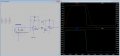
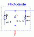
The circuit that was suggested to me on the analog site was this circuit, where I slightly changed the values of the resistor and the capacitor.
 

ericgibbs

Joined Jan 29, 2010
21,531
hi pooya,
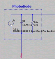
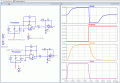
This is one example showing how to reduce the falling edge of the amplified pulse.
Control the Vbias On/Off time and polarity, you will need a fast OPA to create the pulse.
Modify it to suit your project.
Image shows the original version and the modified Vbias for comparison.

E
AAA 1245 18.10.gif
 

Attachments

Last edited:
Top