Circuit analysis with C, D, R and NMOS

Thread Starter

PsySc0rpi0n

Joined Mar 4, 2014
1,786
I have a new circuit to analyse and I wanted to know if is there any way of simulate 3 different frequencies on the same plot.

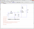
The asc file is attached! Also a printscreens was added!
The desired frequencies are 10Hz, 100Hz and 1000Hz.
 

Attachments

MikeML

Joined Oct 2, 2009
5,444
This is a simple RC discharge circuit. You hardly need a simulator to solve it. If it were a practical circuit, why wouldn't you make the RC product much, much bigger, like 1megΩ and 1uF.

To answer the question of how I would use LTSpice to make plots (if for example, I wanted plots to paste into my notebook), here is what I would do:

1. Create a new parameter, f = frequency in Hz: .param f=10
2. Modify the pulse gen V1 to automatically parameterize the pulse width expression Ton: {0.5/f-2u}
and the period expression {1/f}. Also change the sim directive to .tran {5/f}
3. Run the sim with f=10
4. Plot whatever you are interested in.
5. Change f=100, rerun
5. Change f=1K, rerun

Note that now, changing just one parameter {f} automatically reconfigures the simulator for each new frequency. Anything inside {} curly braces is computed before the simulator runs. It is like a mini programming language.

If you were thinking that the secret to this analysis had something to do with .AC or frequency sweeps, remember that is only for "linear" circuits, where the excitation is sinosoidal (not a varying pulse frequency).

2c.gif

To run the three simulations sequentially so that you can overlay the circuit behavior on one plot, add the directive
.step dec param f 10 1K 1 That will run five cycles of each frequency before allowing you to plot. You will find the plot confusing, however, so I recommend doing it as I suggested above.
 
Last edited:

Thread Starter

PsySc0rpi0n

Joined Mar 4, 2014
1,786
Ok, I just need to ask 2 questions about those parameters!

I didn't understood the .trans 5/f directive! Is that to allow five cycles? If I have chosen like 7 or 2, that would only plot 7 or 2 cycles respectively?

And the other question is when we use the parameter {0.5/f-2u} to set the duty cycle to 50%, on some calculators if we use that expression, they will calculate first 0.5/f and only then it will do the -2u part of the expression! Does LTSpice handles that correctly?
 

MikeML

Joined Oct 2, 2009
5,444
Ok, I just need to ask 2 questions about those parameters!

I didn't understood the .trans 5/f directive! Is that to allow five cycles? If I have chosen like 7 or 2, that would only plot 7 or 2 cycles respectively?
Yes, the expression {5/f} is evaluated before the simulation is run, and is substituted into the .TRAN directive. Remember that Period=1/f, so 5/f is five periods.

And the other question is when we use the parameter {0.5/f-2u} to set the duty cycle to 50%, on some calculators if we use that expression, they will calculate first 0.5/f and only then it will do the -2u part of the expression! Does LTSpice handles that correctly?
Yes, division and multiplication is done before addition and subtraction. It is in the Help file... You can add () if you wish to make the order of operations explicit.
 

Thread Starter

PsySc0rpi0n

Joined Mar 4, 2014
1,786
Ok, thanks...

Tomorrow I'll go into the analytic analysis! I need to show some calcs to the teacher about this circuit!

So I think I need to calculate Vripple, Vc and probably Vds and Id... At least these ones!
 
Last edited:

Thread Starter

PsySc0rpi0n

Joined Mar 4, 2014
1,786
Morning guys...

I have done part of this problem. But now I need to find Vds and Id for the circuit. The problem is that I don't know the K parameter in the datasheet. Is it supposed to be there? Can I solve the problem without K parameter?
 

Jony130

Joined Feb 17, 2009
5,598
Morning Psy,
Which K parameter in the data sheet, I do not see it in the BS170 d/s.?
E
This one


Psy, K parameter want help you much because your MOSFET work in triode region. So you need Rds(on). Also K parameter has a wide spreader from transistor to transistor, even if they have the same part number. And this equation Id = K*(Vgs - Vt)^2 is just a first order approximation (ideal mosfet).
 
Last edited:

Thread Starter

PsySc0rpi0n

Joined Mar 4, 2014
1,786
I think I found a way of getting what I need without the K parameter... I assume that the FET is at triode region, find Id knowing that Vds = 0V in saturation, then with the help of the datasheet figures, I'll find if the assumption is correct or not and explain all this to the teacher!
 
Top