Choosing the correct MOSFET for a low voltage cutoff circuit

BobTPH

Joined Jun 5, 2013
11,609
What is the pass? It has gate, drain, source. It was my understanding that if the source voltage is within the threshold or less than the gate, the drain is 0V. So, I have the gate regulated and as the source drops, once it drops to the threshold, the drain goes to 0V. Is this incorrect? If so, can I get some assistance in this schematic please? It works but the drain is unregulated, which is not what I want.
Well your understanding is dead wrong . The threshold is the voltage at which the MOSFET just starts to turn on, usually passing just 250 uA. And the voltage on the gate above the threshold just increases the current. The voltage on the source or drain depends entirely on the circuit it is in.

Bob
 

LowQCab

Joined Nov 6, 2012
5,101
There are only a few ways that ALL Load can be disconnected
to prevent damage to a Li-Po or Li-Ion Battery.

ANY Current Drain on the Battery will destroy it,
if the Voltage is allowed to remain below a safe level.

You can't do it simply and cheaply without utilizing a "Start" Button.
The "Off" Button is completely optional, because the Circuit will
always turn completely "Off" when the Voltage drops below the set point.
It is quite often a bonus to have
an Under-Voltage-Lock-Out "built-in" to your Power Switch.
The "Start-Button" only needs to be pressed once after the Battery has been charged.

The term "Pass-Transistor" usually refers to a Transistor that is
being used as a "Variable-Resistor",
which is usually carrying significant amount of Current,
such as in a Voltage-Regulator-Circuit, where there may a large, heavy-duty
Transistor that "Passes" most, or all, of the Current from the Input to the Output.
The P-Channel MOSFET in the Circuit I provided is
sometimes referred to as a "Pass-Transistor" because of where it is in the Circuit.

There are Battery Management Chips which can protect the Battery from
under-Voltage, or Over-Charging,
which do not require a "Start-Switch",
but make sure that they are rated to handle the expected maximum Current
that your Circuit will draw from the Battery.
.
.
.
 

LowQCab

Joined Nov 6, 2012
5,101
One part of your question that I missed ..........
""Also, is that 10k resistor from S to G necessary? I thought the P mosfet had something like this built in.""

MOSFETS do not have any "built-in" Resistors.

A FET Gate has virtually infinite Resistance,
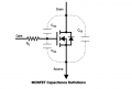
it appears to be a small Capacitor to all of the other parts of the Circuit.

The Gate on ANY Field-Effect-Device MUST ALWAYS BE protected by a Resistor.

With no Resistor, the Gate is considered to be "floating",
and may have any random Voltage on it,
which will cause the device to do crazy things.

If "Static-Electricity" comes into close proximity to an un-protected Gate
the Device may be easily damaged, or even completely destroyed, instantaneously.
You don't get a "second-chance".

In the Picture below, the Resistor "Rg" is not a separate Resistor.
It is the Resistance measured between the Gate-Pin and the actual Transistor inside.
This Resistance generally affects nothing,
except in High-Frequency-Switching applications
where it must be taken into consideration,
because it can affect the Switching-Speed and the tendency towards oscillation.
.
.
.
FET Cap Diagram .PNG
 
@LowQCab Rg is not drawn as a parasitic parameter. Rg is usually required to limit gate current when charging the tiny bitof capacitance unless your using a gate driver. Then you need the high value resistor to ground so leakage currents don;t turn the device on.
 

LowQCab

Joined Nov 6, 2012
5,101
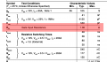
Rg IS a Parasitic Parameter.
The confusion comes when an EXTERNAL Gate-Resistor is quite
often referred to as "Rg" in many Schematics,
especially the Schematics of "Parameter-Test-Circuits" in Data-Sheets.

Most Data-Sheets don't provide the Internal-Gate-Resistance Parameter,
it's usually very small, and can be ignored in most applications.

External-Gate-Resistors generally have 2 functions,

Protecting weak Gate-Drive Components from excessive Current,
such as the average Op-Amp Output,
( which also will not like driving a Capacitive-Load,
and will almost certainly cause oscillations without a Gate-Resistor )

and,

For "tuning" to suppress various Oscillations,
which are usually caused by the desire to use a less than ideal Gate-Driver.

Proper High-Current Gate-Drivers can easily cost more than the FET that it drives.

Very large FETs running at High-Frequencies can require more than ~30-Amps,
in an extremely short spike,
to force them to turn on/off fast enough to be considered "efficient".

"Leakage Currents" may well be a factor that needs to be considered,
but an equally problematic situation is for instance,
what is the state of a particular Circuit's Gate-Drive-Section before it has Power applied to it ?
.
.
.
Gate Resistance .PNG
 
Last edited:

LowQCab

Joined Nov 6, 2012
5,101
It's already pretty slow because of the 10uf Capacitor.
A larger Capacitor could be used, but it would require holding down
the Start-Button for several seconds before the FET will turn "On".
.
.
.
 

LowQCab

Joined Nov 6, 2012
5,101
It is.
The Capacitor delays the cut-off so that temporary Current transients,
which will cause the Battery-Voltage to temporarily sag,
won't be an aggravating nuisance.
.
.
.
 

Wolframore

Joined Jan 21, 2019
2,619
ah, got it… makes sense. I would have just used a cutoff chip with built in hysteresis. Sometimes, it’s not worth the space and trouble but you learn more by building one.
have you thought about how accurate the ADC is and how the discharging battery might affect your reference and regulator output?
 

LowQCab

Joined Nov 6, 2012
5,101
"" have you thought about how accurate the ADC is and how the discharging battery might affect your reference and regulator output? ""
This Circuit is not affected by anything following it, such as the ADC it is powering.
It is extremely accurate, and Temperature-Compensated.
The Capacitor merely "slows-down" any Voltage changes that it detects.
Battery Voltage has zero effect, (other than turning the FET off, of course).

It sounds like You are trying to understand how the TL430 works ..........
It is considered to be an "Adjustable-Zener-Diode",
and is also called a "Voltage-Reference",
but I like to think of it as a Comparitor which switches states
depending only on whether or not the Control-Pin is above or below 2.75-Volts.
Simple, cheap, and easy to work with.

TO-92 Transistor Package, (100ma.),
but is also available in higher-Current-Packages.
.
.
.
 
Top