Choosing optimal voltage and current ripple for boost converter

Thread Starter

zazas321

Joined Nov 29, 2015
936
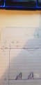
Also, would you be able to explain how does inductor ripple current affect the output current??
Assume continuous mode, higher inductance would result in higher ripple current but the overall rms current will remain the same.

In disciuntinuous mode, does reducing inductor value change the average output current? Or it just shortens the dead time between two cycles
 

BobTPH

Joined Jun 5, 2013
8,998
Think again about the effect of inductor size on ripple current. When the supply voltage is across the inductor, what is the equaton for the change in current during the on period?

Bob
 

Thread Starter

zazas321

Joined Nov 29, 2015
936
It would be (1/L)*integral of Vs.
So that means that the current is inversely proportional to inductance. Please have a look at the picture that I have posted. Assume the same duty cycle but different inductor values. The green represents lower inductance. As it is lower inductance it takes less time to charge so it will charge more than red one, but the average current of both waveforms will remain the same. That is why I am confused about how does the ripple current affect the rms output current
 

Attachments

BobTPH

Joined Jun 5, 2013
8,998
The ripple current on the output is much more dependent on the capacitor. It needs to be large enough to suply all of the output current during the time the inductor is charging.

Bob
 

kubeek

Joined Sep 20, 2005
5,795
What you denoted RMS is actually average, not RMS.
RMS current through the coil will I think be larger than the average current, and will increase with lower inductance due to square of higher peak current not beeing counteracted by the square of the valley current.
RMS current through the load will be entirely different story, and much dependent on the output capacitor and load.
 

Thread Starter

zazas321

Joined Nov 29, 2015
936
I see. Then its much more complex than I expexted. So the RMS would be peak/sqr(2)

. Assume the scenario where we have 2 boost convrrters. Both voltage sources produce same voltage. Assume that duty cycle is the same for both of them.

If I want the load ratio to be different instead of 50/50 which component would I need to change? Lets say I want 60% of energy from first converter and 40% from the second. If I use 40mH and 60mH values respectively, would it change the load ratio?
 

MisterBill2

Joined Jan 23, 2018
18,584
Still no mention at all of the intended application, which application does matter on a power supply. There is a whole lot of information on step up and step down switch-mode circuits at the TI and other websites. Could it be that this is a homework assignment? And now, as I consider some more, 20 volts at 1 amp from either a wind power generator or from a solar cell, only 20 watts, sounds a bit strange. Both wind and photoelectric sources vary, and certainly the variation in voltage will have an effect on the power conversion parameters.
 

Thread Starter

zazas321

Joined Nov 29, 2015
936
The supply voltage is not given neither specified . I can make my own. If i can design it for 20V I will be able to design for different voltage. It is application can be used to charge a battery which can then be converted into AC and put into a grid. But I do not need to worry about that part. I can assume that both sources produce equal voltage and are available 100% of the time
 

Thread Starter

zazas321

Joined Nov 29, 2015
936
I think something is wrong with my PSCAD setttings.
I just cannot understand why the input and the input is on the same level and its nearly 12V even though Input voltage is 10V
upload_2019-1-15_12-24-22.png
 

Thread Starter

zazas321

Joined Nov 29, 2015
936
have done a simulation with the same values on the multisim - get the same results . I am not sure what is it that I am doing wrong :/
 

MisterBill2

Joined Jan 23, 2018
18,584
The supply voltage is not given neither specified . I can make my own. If i can design it for 20V I will be able to design for different voltage. It is application can be used to charge a battery which can then be converted into AC and put into a grid. But I do not need to worry about that part. I can assume that both sources produce equal voltage and are available 100% of the time
Certainly you can select a specific battery voltage BUT in most instances battery voltages come in fixed steps of the individual cell voltages. And that step size depends on the chemistry of the selected battery type. Usually the design of a power system starts with determining the power requirements for whatever will be powered. Then a decision is made as to the time that the loads will need to run, and the system capacity is calculated. And some place in that sequence the acceptable cost of the system is decided. There is often a choice made between systems running with the standard 120 volts mains voltages and appliances and the alternative of the appliances running directly off of the battery array. In many instances the power system is being added to an existing house, in which case usually the choice is to go with the standard mains voltage for distribution.
So generally the exact design of the power converter is far from the first stage of the design.
 

Thread Starter

zazas321

Joined Nov 29, 2015
936
You are going in too much detail than requied for my project.I just litterally need to demonstrate a concept how to design a multiple boost converters with a mixed load ratios. I do not need to worry about what will happe before or after
 

kubeek

Joined Sep 20, 2005
5,795
Ok, so if you want just a "good" number right away for some kind of assignement, then I would go like this: assume the load is allways 20W or nothing, so choose ripple current of twice the average output current. This will let it operate at the border bewteen continous and discontinous mode, and will lead to smallest and cheapest inductor.
Then choose your frquency say 100kHz, and calculate output cap for 5% voltage ripple. Why? Because I said so ;) Not enough parameters, so the only informed choice you can make is about the inductor, and even that is with the added assumption about load.
 
Top