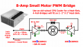
Choices about my H-bridge DC motor driver

Irving

Joined Jan 30, 2016
5,195
You need to start with the robot mechanics to size the motor to inform the electronics. Doing it any other way almost always leads to disappointment and a restart. Sadly seen too many student projects fail because of that.

I've been doing mechatronics since before it was called that. I now teach mech & electronics to students on our Biomechanical Engineering: Rehabilitation Engineering & Assistive Technology MSc. Mainly medics and clinicians who want to translate clinical research to practical technological solutions.

MATLAB scripts never solved anything... If you don't have a grasp of the underlying principles how do you know if they're right or not?
 
Last edited:
Thread Starter

Ephex

Joined Jul 4, 2021
83
What you are saying is correct, and I totally agree with you.

However, all I wanted to do is to make an H bridge DC motor driver that's powered by 10-12 V. If I (or someone of my friends) find that it is suitable for another project (like a robot) when it's done, it will be used in that project. If not, I will just test it on some 12 V motors to see if the driver works. I intentionally began with the wrong component of a system.

The reason I started this project was not to make a robot and then design an H bridge motor driver that will be able to handle the kind of motors that's going to be used in that robot. wanted to try out designing a circuit that's functional, and order a PCB that's not with 100% through hole mounted components (like all my other PCBs have been), but with mainly SMD.

One thing I don't agree with on the other hand, is that "MATLAB scripts never solved anything". It might not solve any problem you throw at it, but I've had very good experiences with MATLAB. We used it in a System Engineering course to calculate everything in our (theoretical) vehicle all the way up the "chain" from our specifications like wanted acceleration and therefore wanted angle acceleration on the wheels, to what kind of PSU is needed.

If we needed to change a parameter, we could just switch the value of the right variable and run the script again, not needing to do all the calculations by hand. And boom, we had around 8 graphs displaying how it performed over our "test environment" with steep up- or down hills.

Now it won't be, and wasn't, a 1:1 representation of what reality is, but I think it gives a good approximation of an overview of the whole system.

If you don't like MATLAB and don't think it solves things, that's fine. You have more knowledge and experimence and have a better view of what engineering tools are useful/less useful. But I like MATLAB, and have had great experiences with it in all of our courses : )

I hope I didn't come of as a "know-it-all" cocky engineering student. You have helped me immensly with this, and I want to thank you one more time.
 

Irving

Joined Jan 30, 2016
5,195
One thing I don't agree with on the other hand, is that "MATLAB scripts never solved anything".
Ok, that was a throw away response and probably didn't come across well! I have a lot of time with MATLAB and use it a lot. What irks me are some 'educators' provide scripts that 'do it all for you' without ensuring that their students have sufficient grounding to know how to do it without the script and, more importantly, can look at the numbers and validate that they are in the right ballpark. I've seen too many projects go awry over the years (and I mean some big commercial ones) because no one did a sanity check on the output of some 'script'. And we all know the story of the NASA probe that crashed because of a confusion between metric and imperial units - that was the headline, but the whole thing was validated by 'scripts' so no one picked up the error...

I get where you're coming from, though I would have still approached it from a real-world problem point-of-view.
 

Thread Starter

Ephex

Joined Jul 4, 2021
83
Update:

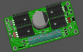
The PCB is now ordered!

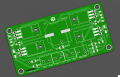
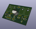
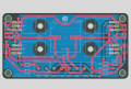
1626007325223.png1626007422656.png

The mosfets didn't have a 3D file, and 3 out of 4 connector blocks are rotated the wrong way in the 3D view lol.

The website I planned on ordering components from apparently only sold to companies, so I had to find this SOT-23 mosfet (also found this one) for Q5 and Q6. For the 2 main N-channel mosfets (to substitute for PSMN017-30PL,127) I found IRLZ44NPBF, which I suppose are like IRLZ44N? The data sheet for it looked good in my eyes.
 

Irving

Joined Jan 30, 2016
5,195
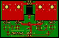
A few comments on your PCB if I may. Though I can't see the reverse side, which I'm guessing has a ground plane, you missed a trick with not filling a Vcc zone on the top side. So you have a track from the + of C1 to the source the (upper left MOSFET but then a long spindly track all the way to the source of the upper right MOSFET. You need to keep the supply and motor tracks as short, thick and as balanced as possible. Also, consider flood filling the area under the MOSFETs to give some heatsinking, if you're not mounting them vertically so you can use a push-fit heatsink. Finally, the upper and lower MOSFET on each side have common drains, so a little rearrangement can remove tracks and replace with heatsink zones on both front and back, with thermal vias between them. Another issue is that you really need a signal ground for the inputs; you should avoid sharing power and signal grounds through the same connection if possible.

Here's my quick interpretation....

1626086340418.png

1626086983353.png
 
Last edited:

Thread Starter

Ephex

Joined Jul 4, 2021
83
I do have a ground plane on the back side, but I'll keep everything you said in mind for the next version. I'm crossing my fingers it'll work atleast!
 

Irving

Joined Jan 30, 2016
5,195
Oh it'll work, at least for small motors in the 100-500mA bracket. With the bigger motors your MOSFETs will be dissipating between 0.25 and 0.5W roughly so the junction & case will be approx 20 - 40degC above ambient with no discernable heatsink. You might get some 'ringing' on the MOSFETs as they switch off - this can be an issue as it stops them turning off fully quickly and runs the risk of shoot-through. That's partly the effect of parasitic inductance of the long source connections.
 

Thread Starter

Ephex

Joined Jul 4, 2021
83
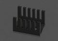
The 4 black parts are the aluminum heatsinks I'll be using. They'll be mounted between the MOSFETs and the PCB (probably not the best way to mount but there are atleast aluminum "sticks" poking up).

1626090424107.png1626090201543.png
 

Thread Starter

Ephex

Joined Jul 4, 2021
83
Hey guys!

Here comes an update. Turns out I'm going to bother you a bit more!

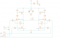
dc motor driver.PNG

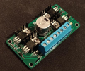
The PCB arrived this month and I soldered it together and tried it out. However, I had not made sure that REV was actually 0V when running FWD. This must have made the mosfet experience a floating value, possibly keeping it open instead of closing it. The motor I had connected worked for a few seconds and I could adjust the speed with a PWM signal from an Arduino Nano. However, it started smoking. I had ruined that part of the circuit, so I switched to control the REV portion instead. This worked in the same way, but also ended up in smoke and the top VCC line popping up, ruining the PCB.

Today I used one of the other 4 PCB copies that arrived with the shipment and soldered together a new one with new components (exept for the large capacitor and heatsinks). This time I made sure FWD was 1 and REV was 0 when I wanted to go forwards and vice versa with reverse. On the other hand, it did not work. I doublechecked everything and it seemed fine, so I started measuring voltages. Signals were fine, the PWM signal was changing based on the Arduino etc. Here comes the interesting part. In this video you can see me measure some voltages with the motor not running, but the PWM being roughly 50% in a state where it was supposed to work. When I measured the voltage between GND and the drain of one of the P-channel mosfets, the motor rushed to speed and stabilized at the speed given by the PWM signal.

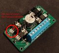
It turns out, I shorted the drain and source with the multimeter probe when trying to measure! That started in some way up the motor, giving me control with the PWM signal! I could control it with no problems, no smoke, no overheating whatsoever. However, when turning the PWM signal to 0%, the motor stopped and was stuck at 0 rpm regardless of what I changed the PWM signal to after that. Here's the exact mosfet this occured on:

dc motor driver info.jpg

TL;DR: The circuit works, but the motor needs to be started before you can control it. Shorting the drain and source of a mosfet rushed the motor to start, giving control until you made it stop.

How does one try to find out why it's not starting by itself? The PCB does work, not just always lol. I have a multimeter but sadly no oscilloscope if that's useful in these situations. Do you guys have any ideas on what can be the problem?

Extra info and pictures gathered here so you don't have to search too much in this thread:

Note, the components have equivalent/similar components on the circuit due to shortages when ordering.

The ones I used on my PCB:
D1 and D2
The top two MOSFETS [ IRF5210PBF ]
The bottom two MOSFETS (IRLZ44NPBF)
Q5 and Q6 (small SOT-23)

1627761223234.png

1627761256174.png
 

Irving

Joined Jan 30, 2016
5,195
TL;DR: The circuit works, but the motor needs to be started before you can control it. Shorting the drain and source of a mosfet rushed the motor to start, giving control until you made it stop.

How does one try to find out why it's not starting by itself? The PCB does work, not just always lol. I have a multimeter but sadly no oscilloscope if that's useful in these situations. Do you guys have any ideas on what can be the problem?
There could be several issues; for a start, what happens if you turn it on turn up the pwm - motor still not running - then spin the motor gently in the direction it should be spinning? does it pick up?

A scope is always useful..
 

Irving

Joined Jan 30, 2016
5,195
What it means is your not giving the motor enough amps to get it turning. That could be for several reasons from not turning on the MOSFETs hard enough to simply not having a long enough 'on' period to allow current to ramp up far enough, and that could be because your supply volts is too low for PWMing those motors...
 
Top