Chicken coop door circuitry with lamp timers

Thread Starter

jmh226

Joined Nov 7, 2015
34
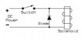
A 1n4007 would be OK, for the coils.
Polarity is important.
Max.
Which direction should the line be, + or - ? And is this a necessary addition, or just best practice? What will/may happen if I skip it? Not trying to be difficult, just trying to learn :)
 

MaxHeadRoom

Joined Jul 18, 2013
30,763
Stripe end to +ve supply on the coil.
upload_2015-11-9_15-18-54.jpeg
The diode prevents the back emf spike that occurs when you turn off the relay, in solid state circuits it can cause a problem in particular.
Max.
 

MikeML

Joined Oct 2, 2009
5,444
What is the motor voltage rating?
How much current does it take to start the motor?
How much current does it take to run the motor once it comes up to speed?
Is your wall-wart iron-transformer plus rectifier or is it a switch-mode power-supply (What is its input voltage range?)
How many Watts does it take to run your timer(s)?
What country are you in?
 

Thread Starter

jmh226

Joined Nov 7, 2015
34
What is the motor voltage rating?
How much current does it take to start the motor?
How much current does it take to run the motor once it comes up to speed?
Is your wall-wart iron-transformer plus rectifier or is it a switch-mode power-supply (What is its input voltage range?)
How many Watts does it take to run your timer(s)?
What country are you in?
The motor is 12VDC
The current to start with no load: 0.36A - measured with the current clamp on my multimeter
The current while running with no load: 0.20A - measured with the current clamp on my multimeter
I have two different transformers:
one has an input voltage range of 100-240VAC, outputs of 12VDC, 1.5A & 5VDC 2.5A
the other has an input voltage of 100-120VAC, output of 12VDC, 1.25A
The timers run at .00564Watts (120V x 47uA - measured through my multimeter)
I am in the USA

While attempting to measure the DC amperage of the motor, I kept on getting a phantom reading in my current clamp on the multimeter, so I had to use the zero button...I've never had this issue with AC current measurements. The motor documentation indicates that the motor pulls 0.85Amps (http://www.surpluscenter.com/Catalog/Catalog288-149.pdf) item#5-1683
 

MikeML

Joined Oct 2, 2009
5,444
The timers draw insignificant power. The "transformers" are actually switch-mode power supplies which draw insignificant power when the 12Vdc side is not loaded. The motor draws very small power only while in motion; draws zero power after it trips either limit switch. The limit switch relays draw power continuously?

One more question about the timers: they run on 120Vac, but do they have an isolated switch contact output (four or more wires/contacts), or do they just switch 120Vac (only three wires/contacts)? Model number?
 

Thread Starter

jmh226

Joined Nov 7, 2015
34
How did you know that the "transformers" were switch-mode power supplies based on the input voltages? What would the input voltages have been if they were true transformers?
 

MikeML

Joined Oct 2, 2009
5,444
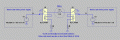
Assuming you have two timers, two dc power supplies, two spst 12Vdc relays, with two normally-closed limit switches, this is about as simple as I can make it:

chicken.gif
 

MikeML

Joined Oct 2, 2009
5,444
How did you know that the "transformers" were switch-mode power supplies based on the input voltages? What would the input voltages have been if they were true transformers?
If they are "real transformers", they are heavier, and the input voltage would have been 120Vac +- 10% or less.
 

Thread Starter

jmh226

Joined Nov 7, 2015
34
Assuming you have two timers, two dc power supplies, two spst 12Vdc relays, with two normally-closed limit switches, this is about as simple as I can make it:

View attachment 94408
Wow - I am impressed! This looks really excellent! On a practical wiring note, just to confirm, the striped wires coming out of my wall warts are the +V right? and can I literally wire nut all of the grounds shown on your diagram together and to both of the solid wires on the wall warts (I think yes), or do I need to actually run them into the ground prong on the wall outlet(I think no)? Or do I need to wire some to the solid wire on one wall wart and some to the solid wire on the other wall wart (I think no)? Sorry - this is my first DC project!
 
Last edited:

MikeML

Joined Oct 2, 2009
5,444
The ground symbol in my schematic is not water-pipe (green-wire) ground; it is just short-hand for "tie-all-of-these-points-together"! It is really 0V in the DC schematic.

How far is it from the timers/wall-warts to the chicken coop door? If more than dozens of feet, then you might want to tie the 0V line to a water-pipe ground for lightning protectection.

Presumably, the wall-warts have complete galvanic isolation (infinite Ohms between either AC prong and any secondary DC wire?

Plug-in the wall wart(s), and use your VOM in DCV mode to check the polarity between the wires... Whatever wall-wart wire the black VOM lead is connected to make the meter read +12V is the one that ties to the ground symbol in the schematic.
 

MikeML

Joined Oct 2, 2009
5,444
Just to clarify, when I said "normally closed limit switch" in the schematic, I mean that when the door is in a position about halfway between fully-up and fully-down, both limit switches are closed! One opens when the door arrives at its respective limit...
 
Last edited:

Dodgydave

Joined Jun 22, 2012
11,395
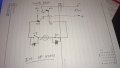
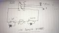
You only need one psu, the timer activates the change over relay for the coop door up, down, the only power that will be wasting is the relay when activated, the motor will switch itself off with the limit switches like this..

Door open..

DSC_0044.JPG


Door closed..

DSC_0043.JPG
 

Thread Starter

jmh226

Joined Nov 7, 2015
34
I'll be installing MikeML's circuit design today and will let you all know how it goes :) Thanks so much for all of the help!

My next project will be a remote monitor for the levels of water and food in the coop if you're interested in helping me tackle another one :)
 

Thread Starter

jmh226

Joined Nov 7, 2015
34
Might be a little OTT but could one of the automatic pool level maintainers work?
Or make on on the same principle.
Max.
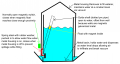
This is a possibility for the summer months, but I live in upstate New York, USA where winter temperatures are consistently (and significantly!) below freezing, so any waterline to the unheated coop would freeze in the winter. My idea for the physical part of the waterer is diagrammed below. The metal housing/basin arrangement is a typical poultry waterer and I already have it. What I really need help with is how to get a signal from the switch in the coop to my house roughly 90' away, ideally wirelessly so that I can just check some kind of inside receiver to see if the chickens need water. I have no idea where to even begin in dealing with wireless transmission of signals - but that would be the holy grail so that I don't have to needlessly go outside to check the chickens when it is 10 degrees F out there and snowing!
chicken waterer.png
 
Top