Check my newbie circuit. Lighting leds in sequence with delay

Thread Starter

replicaprops

Joined Jul 1, 2017
28
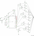
The schematic does not show any current limiting resistors for the LEDs, and all LEDs in direct parallel. That will not work. I notice that the pc board layout addresses both issues. Do you have that schematic?

ak
This is how I redrew it in fritzing.
light up key_schem.png
And this the pcb with the ground fill put in.
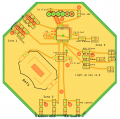
light up key6pin_pcbgf.png
 
Last edited:

WBahn

Joined Mar 31, 2012
32,991
Just so the OP knows how much that might be. In the US, an experienced contract design engineer would likely charge around $250/hr; 3 days would be $6000.
Though a design like this doesn't require such an experienced engineer. An engineer charging those kinds of rates would probably be expected to do everything in half a day or so. The have the experience and the tools and the skills to do it very quickly -- which is why they can justify such a rate.

One the other end (staying local) you can probably approach a university and talk to a couple of EE profs and find a senior to do it in less than a week for $100 and a six-pack or two. It looks good on a new grads resume and make a decent talking point on an interview.
 

Thread Starter

replicaprops

Joined Jul 1, 2017
28
Though a design like this doesn't require such an experienced engineer. An engineer charging those kinds of rates would probably be expected to do everything in half a day or so. The have the experience and the tools and the skills to do it very quickly -- which is why they can justify such a rate.

One the other end (staying local) you can probably approach a university and talk to a couple of EE profs and find a senior to do it in less than a week for $100 and a six-pack or two. It looks good on a new grads resume and make a decent talking point on an interview.
There are hundreds of engineers on fiverr. That is where I found the fellow who did this for me.
 

WBahn

Joined Mar 31, 2012
32,991
I hired a engineer in Pakistan. He supplied the schematic. He used Eagle, but I did not know how to use eagle, so I tried to duplicate the schematic in Fritzing. This is the schematic he supplied to me.

He delivered in a few days and charged me $50 for everything.
The schematic doesn't match the PCB very well. The schematic shows the LEDs in parallel with no current limiting resistors.

Are you sure you want to use that ATMEGA328 part? It's going to cost you about $1.50 more than the PIC. If you are only making ten of these, that's $15 off your bottom line. If you are making hundreds of these, that becomes significant. Consider what that extra cost does to your profit margin before proceeding. If your willing to accept it, then that's a choice you are certainly ffree to make.
 

Thread Starter

replicaprops

Joined Jul 1, 2017
28
The schematic doesn't match the PCB very well. The schematic shows the LEDs in parallel with no current limiting resistors.

Are you sure you want to use that ATMEGA328 part? It's going to cost you about $1.50 more than the PIC. If you are only making ten of these, that's $15 off your bottom line. If you are making hundreds of these, that becomes significant. Consider what that extra cost does to your profit margin before proceeding. If your willing to accept it, then that's a choice you are certainly ffree to make.
I get 10 of the mcus from aliexpress for $10. This is a hobby, so im not out to make a fortune.
 

AnalogKid

Joined Aug 1, 2013
12,188
That's what you proposed on day 1. I was trying to do it with one cap and was struggling with the last half second delay.
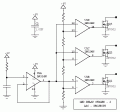
Something like this? The resistor string can set the trip points starting at 0.5RC to keep things away from the compressed top end of the curve. Since the opamps contribute only input offset voltage error, timing should be more repeatable than the CMOS inverter version.

ak
LED-Delay-2-c.gif
 

Attachments

dendad

Joined Feb 20, 2016
4,641
You still have the reset resistor / capacitor wired wrong on you PCB. (R14 and C2)
Have a good look at R2 and C2 on the supplied circuit.
 

dl324

Joined Mar 30, 2015
18,421
He delivered in a few days and charged me $50 for everything.
Foreign labor is cheap; that might have been a months wages for him.

A couple months ago, I had a plumber tell me he'd charge me $250 just to knock on my door. The last work I had done by a plumber cost me $200/hr; to replace some galvanized pipe. Once I found out they use CPVC instead of galvanized pipe, I've done all of my own plumbing since then. The only time I'll use a plumber is if the job requires a permit; which they can pull for 10% of what it would cost me. Otherwise, plumbing ain't rocket science and I haven't run into any job I couldn't do myself.
 

Thread Starter

replicaprops

Joined Jul 1, 2017
28
You still have the reset resistor / capacitor wired wrong on you PCB. (R14 and C2)
Have a good look at R2 and C2 on the supplied circuit.
Thanks, I just sent the engineer an email to check that and see what I did wrong. I appreciate you pointing that out. Hopefully he can tell me how to fix the problem.
 

dl324

Joined Mar 30, 2015
18,421
Something like this?
Yup.

OP is operating from 3V, so might have needed to use BJTs. I would have used LM339 and the common mode input range is crap with a 3V supply; only guaranteed for 0-1V over the full temperature range. That means the RC time constant needs to be largish so all trip voltages can be under 1V.

Since it's operated from a 3V coin cell, could skip the current limiting resistors and put as many LEDs in parallel as he wanted. It's generally a bad design practice, but you can cut corners on an LED blinker to save manufacturing cost.
 

dendad

Joined Feb 20, 2016
4,641
Just another thought..
Are you going to use pre-programmed chips with the Arduino boot loader installed? If not, you will need to have an ICSP connector on the board else you will not be able to program it.
 

dendad

Joined Feb 20, 2016
4,641
That looks better :)
And the programmer adapter looks good too. I hope you do well with this project. Please let us know.
 

Thread Starter

replicaprops

Joined Jul 1, 2017
28
That looks better :)
And the programmer adapter looks good too. I hope you do well with this project. Please let us know.
Thank you. It wasnt until I saw a video where a guy explained why the cap and resistor were where they are and how it acts as a reset switch that I comprehended the pull up. Ive ordered all the components, so as soon as I make sure my footprints are accurate, ill order the boards. I'll make sure to post with the complete project.
 

dl324

Joined Mar 30, 2015
18,421
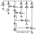
With a single timing ramp you need three trip point values somehow. Three transistors with three different zener diodes (or numbers of silicon signal diodes) in series with the bases will work, although that is a rather low impedance approach that will drive up the size of the capacitor.
Had some time. Here's the single RC, 4 transistor approach.
upload_2017-7-20_19-37-33.png
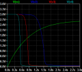
Simulation gave delays of about 0.5, 0.8, and 1.5 seconds. Ran the simulation on a different computer. Will post later.
EDIT: Circuit timing. V2 = Q2 collector, V3 = Q3 collector, V4 = Q4 collector, Vc = timing cap
upload_2017-7-20_19-59-10.png
 
Last edited:
Top