Facebook
 Google
 GitHub
 Linkedin
I'm confused with the electrical issue I have on my car.
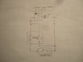
This is a situation:
1 - originally, the gas strut (hatch) is "wired" and acts as a light switch: when the hatch is closed, the strut is compressed, the circuit is open - no lights.
2 - when the hatch is open, the gas strut is extended and the contact is made to complete the circuit - the light is on.
3 - I had to remove this strut, so I needed to find another way to trigger the light.
4 - I ran a magnetic reed switch NO (normally open) when the magnet is next to it.
5 - the magnet moves and the reed switch closes the circuit - the light is on.
Simple in theory, but... This reed switch gets stuck after it's on for more than a few seconds. I assume that it "burns" and its contacts "weld" together. This reed switch is rated 0.5A 12VDC.
So, I added a relay, 12VDC, 1A, so the reed switch activates the elec. magnetic coil in relay and the relay completes the circuit, carrying more amperage.
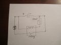
I bench-tested this set up using scooter's 12V battery, relay, reed switch, light and wires... all works well - as intended.
When I installed this set up on the car WITH REED SWITCH POWERED SEPARATELY FROM CAR'S WIRING (USING SCOOTER'S BATTERY), the light tuns on. All works as intended.
BUT... when I power the reed switch from the car's circuit, shared by the relay switch and the light, the relay starts to buzz or chatter. Adding a 470mF capacitor in parallel with relay coil terminals "slows" the rate of chattering. 2 capacitors in parallel slow it even more. I thought that reed switch doesn't pass enough current (amps) to keep the relay's coils "closed".
then... I tried to use a different relay, about 0.2A 12VDC - same problem.
What am I doing wrong?
I tried different resistors, all they do is dim the light, but chattering remains.
What do I need to do to fix this problem? and how?
This is a situation:
1 - originally, the gas strut (hatch) is "wired" and acts as a light switch: when the hatch is closed, the strut is compressed, the circuit is open - no lights.
2 - when the hatch is open, the gas strut is extended and the contact is made to complete the circuit - the light is on.
3 - I had to remove this strut, so I needed to find another way to trigger the light.
4 - I ran a magnetic reed switch NO (normally open) when the magnet is next to it.
5 - the magnet moves and the reed switch closes the circuit - the light is on.
Simple in theory, but... This reed switch gets stuck after it's on for more than a few seconds. I assume that it "burns" and its contacts "weld" together. This reed switch is rated 0.5A 12VDC.
So, I added a relay, 12VDC, 1A, so the reed switch activates the elec. magnetic coil in relay and the relay completes the circuit, carrying more amperage.
I bench-tested this set up using scooter's 12V battery, relay, reed switch, light and wires... all works well - as intended.
When I installed this set up on the car WITH REED SWITCH POWERED SEPARATELY FROM CAR'S WIRING (USING SCOOTER'S BATTERY), the light tuns on. All works as intended.
BUT... when I power the reed switch from the car's circuit, shared by the relay switch and the light, the relay starts to buzz or chatter. Adding a 470mF capacitor in parallel with relay coil terminals "slows" the rate of chattering. 2 capacitors in parallel slow it even more. I thought that reed switch doesn't pass enough current (amps) to keep the relay's coils "closed".
then... I tried to use a different relay, about 0.2A 12VDC - same problem.
What am I doing wrong?
I tried different resistors, all they do is dim the light, but chattering remains.
What do I need to do to fix this problem? and how?