Charging circuit detection Craftsman tractor

Thread Starter

Eavedesian

Joined May 2, 2019
5
Hey all, I've got an early 90s tractor with a charging detection circuit that the part is obsolete. So I figured I could make my own.

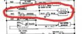
Here is a capture of the wiring diagram:

20190502_112843.jpg

I've located a simple circuit that I thought might work:
Screenshot_20190430-171138_YouTube.jpg

I know this circuit shows the + switched and I need to make the - switched.

However, because of the hysterisis on the relay it does not deenergize the relay when the voltage falls below 12.6ish volts.

Outside of experimenting with higher voltage zeners would I be out of luck of building this without adding a transistor?

I really didnt want to add a project box and such to make this work.

Thanks in advance for any insight.
 

Attachments

Ylli

Joined Nov 13, 2015
1,086
The Zener is upside down. When do you want the light on? When the battery is low or not being charged? When the battery is being charged? When the battery is being overcharged?

IOW, voltage at which you want the light to come on, and the voltage you want to light to go off.
 

BobaMosfet

Joined Jul 1, 2009
2,110
It would help to see the schematic WITHOUT the red circle on it. Not sure what you're problem is- did a relay fail, or? A relay is an inductor, so it's going to take time to kick in, and it's going to kick some voltage back when it's released. What are you trying to achieve, charge your battery when it needs it, or just turn on a lamp letting you know it's dishcarging or...?
 

Thread Starter

Eavedesian

Joined May 2, 2019
5
Thanks for all the replies! I want the light to come on when the voltage falls below 12.6ish and go off above. I'm attaching the full original diagram.

I figured the zener was backward. Lol. I'm thinking the current limiting resistor might be causing an issue as well.

Also the coil resistance for the relay is about 80 ohms.

The reason why I dont want to use a LED is that i wanted to keep the dash lights on this thing original.

Screenshot_20190408-113508_Chrome.jpg
 

crutschow

Joined Mar 14, 2008
34,282
I think you will need to add a transistor to get the results you want.
Below is the LTspice simulation of a circuit with a transistor and Zener diode.
The 1k ohm Pot U1 allows adjustment of the trigger point.
The 5.6V Zener has a positive temperature coefficient that cancels much of the negative coefficient of the transistor base-emitter voltage to make the circuit fairly insensitive to ambient temperature change.

The circuit can be built on a small perf board.

upload_2019-5-5_13-13-40.png
 
Last edited:

Dodgydave

Joined Jun 22, 2012
11,284
Why not just put a TL431 zener in series with a Red led across the battery....with R2 at 1K and R1 a 4K7 preset, set the preset to your desired on voltage...


12v-battery-monitor-with-tl431.jpg 12v-battery-monitor-with-tl431.jpg
 
Last edited:

Thread Starter

Eavedesian

Joined May 2, 2019
5
Yes, light needs to be on when voltage is low. Also I wanted to use the regular incandescent bulb in the original location.

I have a BASIC electronics background. I mean BASIC. However, I thought a Zener wouldnt conduct if the voltage was below its specific value when installed in reverse bias.
 

Ylli

Joined Nov 13, 2015
1,086
You could use Crutschow's circuit and just connect the lamp to the NC relay contact instead of the NO contact. Or you could add a relay with diode similar to Crutschow's curcuit to DodgyDave's circuit in place of R3, R4, and the LED.
 

crutschow

Joined Mar 14, 2008
34,282
I thought a Zener wouldnt conduct if the voltage was below its specific value when installed in reverse bias.
That's true.
Where do you think it's otherwise?
In the circuit I posted, the relay is off when the voltage is below the trigger point.
Above the trigger point, the Zener conducts, turning on the transistor and energizing the relay.
 
Last edited:

crutschow

Joined Mar 14, 2008
34,282
Or you could add a relay with diode similar to Crutschow's curcuit to DodgyDave's circuit in place of R3, R4, and the LED.
You would also need to add a transistor.
The TS's relay coil resistance is 80Ω, giving an operating current of over 150mA, and the TL431 is rated for only 100mA maximum recommended current.
 

Thread Starter

Eavedesian

Joined May 2, 2019
5
That's true.
Where do you think it's otherwise?
In the circuit I posted, the relay is off when the voltage is below the trigger point.
Above the trigger point, the Zener conducts, turning on the transistor and energizing the relay.
The original diagram I posted showing the zener in forward bias. I know that was backwards but I thought it should work without a transistor.
 

Ylli

Joined Nov 13, 2015
1,086
The original diagram I posted showing the zener in forward bias. I know that was backwards but I thought it should work without a transistor.
Swapping around the Zener in your original circuit...

The Zener and the series diode produces a standoff of about 13 volts. If the battery is below 13 volts, the relay would not be pulled in and your light would be on. But what happens when the battery voltage is at 15 volt - certainly a value indicating it is getting a good charge? You want the relay to pull in and your light to go off. But with 15 volts in, and a 13 volt standoff, you have only 2 volts on the relay coil. Is that going to pull in your relay?
 

crutschow

Joined Mar 14, 2008
34,282
If you wanted to use just the relay, you could try adding a 1W, 100Ω pot in series with the relay coil and adjust it to the desired pull-in voltage.
But the difference between the pull-in and drop-out voltages could be several volts.
 
Top