Facebook
 Google
 GitHub
 Linkedin
Hi shortbus I'm glad to hear your doing ok, I still wake up breathing so that's always a good sign lol.
Cheers.
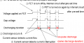
I hate to disagree with you here as both types of motor can use the same voltage feedback control method to monitor the z axis position and therefore both types are as good as each other but a stepper motor will probably last longer than a brushed DC motor. I don't know if you've seen my latest video on YT testing the new design mosfet power generator but that test machine is the original Easy-Peasy machine that I built back in 2017 and it still works great with just as stable a "burn" as my stepper motor version of EDM which is surprising considering it's just a couple of cheap XY slide tables from China mounted on an old drill stand.His designs use a small gear motor, with them there is no real control so they spend a lot of time shorting out and then retracting. A stepper motor can be set to only advance a small amount and not short out the burn. Each time it shorts out it leaves a slight mark in the finish.
Cheers.
")