Facebook
 Google
 GitHub
 Linkedin
Hi:
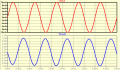
I don't understand why the output voltage has a maximum positive peak of
600 mV and a maximum negative peak of -700mV.
I have experimented by varying the Q-point but no luck.
Any help would be appreciated.
David
I don't understand why the output voltage has a maximum positive peak of
600 mV and a maximum negative peak of -700mV.
I have experimented by varying the Q-point but no luck.
Any help would be appreciated.
David
Attachments
-
2.1 KB Views: 29
")