CD4098 Monoshot negative edge trigger problem

Thread Starter

maanas.adi

Joined Nov 3, 2011
12
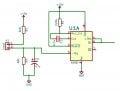
Pls see the circuit attached. The input is through a contactor which when closes starts charging the capacitor. ideally when the capacitor discharges, then a pulse should be generated at +Q. But the problem is as soon as Capacitor voltage reaches nearby 8-9 volts while charging a pulse is generated at +Q. What is the reason behind that and how can I remove this problem. Do I have to put schmitt trigger in between? Thank you
 

Attachments

Thread Starter

maanas.adi

Joined Nov 3, 2011
12
hi,
It could be that the cap charge rise time is too slow and it unstable at the 8V>9V level and its triggering the 4098.
E
So, I have to decrease the rise time. i.e. charge the capacitor as fast as possible. BTW what can be considered minimum rise time so not to have output pulse during capacitor charging.
 

DickCappels

Joined Aug 21, 2008
10,180
B-series CMOS tends to oscillator with slow rise and fall time inputs. The Schmitt trigger should clean things up. About 50 years ago I tried using an A-series schmitt trigger to trigger logic when the sun set.

After a failure that required going up into the foothills to retrieve the transmitter that failed to come on, I put all six of the Schmitt triggers in the package in series and finally got the sharp edge I needed. Your mileage may vary.
 

atferrari

Joined Jan 6, 2004
4,770
B-series CMOS tends to oscillator with slow rise and fall time inputs. The Schmitt trigger should clean things up.

After a failure that required going up into the foothills to retrieve the transmitter that failed to come on, I put all six of the Schmitt triggers in the package in series and finally got the sharp edge I needed. Your mileage may vary.
Hola @DickCappels

Why six and not just one?
 

DickCappels

Joined Aug 21, 2008
10,180
One did not produce the fast risetime pulse that I needed. I came to suspect that the Schmitt triggers were not truly Schmitt triggers.
 

atferrari

Joined Jan 6, 2004
4,770
One did not produce the fast risetime pulse that I needed. I came to suspect that the Schmitt triggers were not truly Schmitt triggers.
I see. I recall implementing my first Schmitt trigger using "as is" the circuit shown in Wikipedia at that moment and worked perfectly.
 

ScottWang

Joined Aug 23, 2012
7,400
One did not produce the fast risetime pulse that I needed. I came to suspect that the Schmitt triggers were not truly Schmitt triggers.
The IC technology today and old day is different, maybe you can try it again, does it still needs to use two more Schmitt triggers?
 

danadak

Joined Mar 10, 2018
4,057
You have a large C attached to a CMOS input. Depending on how power
is removed from circuit its possible that will discharge thru input protection
diodes on CMOS input and cause damage. You should have a limiting R
in series from C to CMOS input to limit current.

Spec is ~ 10 mA DC input current on any pin.


Regards, Dana.
 

AnalogKid

Joined Aug 1, 2013
11,044
Try to connects +TR1 to Ground.
This is good advice. As shown in the datasheet application circuits, unused trigger inputs *must* be tied to their inactive state. This means that in your circuit, the unused TR+ input must be tied to GND (Vss).

Also, your schematic does not show a decoupling capacitor for the chip. Use a 0.1 uF to 1.0 uF ceramic cap connected as close as possible to the Vdd and Vss pins, with short leads


ak
 

eetech00

Joined Jun 8, 2013
3,951
Hello,

You really should use a CD14538B chip. Its can replace the CD4098B and has Schmitt trigger inputs.
The trigger rise/tfall time is limited to 100us for the CD4098B. The CD14538 trigger trise/tfall is unlimited.

In your diagram.
1. The input resistor (R2) should be reduced to 680 ohms or less because it forms a divider with the 68k (R3) and drops too much voltage. What discharge trigger point are you looking for?
2. The Q output should be connected to the +TR input. This prevents the timer from re-triggering.
3. The R1C1 combination provides a pulse width of about 22ms. Is that what you want?

See attached example showing the CD14538B.
In the example, the simulation starts with the contactor open for 1 sec. The contactor then closes for 1 second, then re-opens. Upon opening, the capacitor discharge triggers the timer.

eT

upload_2019-9-28_9-40-19.png
 
Top