Carwash Vendo Timer Custom PCB

Thread Starter

christiancamano

Joined Sep 23, 2025
5
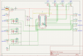
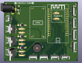
Can anyone tell me what components am I lacking or should I add to make this PCB complies with electronics principles.


-12v Input
with reverse polarity diode
-LM2596S for stepdown to 5v for ESP 32 Dev Board Input
-ESP Wroom 32 30 pins Development board
-1 coin acceptor
with with 2 resistors for voltage dividing to 3.3v
1 buzzer
-4 TM1637 Displays for Credit, and 3 functions (right side)
- 3 buttons with LED for Function activation (bottom)
-3 outputs for relay (left side)
mosfet driven IRLZ44N with resistors and flyback diodes.
-1 12v output for LED frame of Coin acceptor.
 

Attachments

Last edited by a moderator:

be80be

Joined Jul 5, 2008
2,395
Forget optoisolators it not last a month in a carwash i fix carwash equipment for 9 years now heat and water. opto's are good but the esp is not harden enough I been playing with lighting the esp would die fast i switched to a pico w it lasted 5 months as of now there only 5 bucks and can do the same stuff the ESP can but they seem made a lot better
 

Thread Starter

christiancamano

Joined Sep 23, 2025
5
Forget optoisolators it not last a month in a carwash i fix carwash equipment for 9 years now heat and water. opto's are good but the esp is not harden enough I been playing with lighting the esp would die fast i switched to a pico w it lasted 5 months as of now there only 5 bucks and can do the same stuff the ESP can but they seem made a lot better
Please share what had been the reason why ESP is failing fast on your projects.
 

be80be

Joined Jul 5, 2008
2,395
The ESP 32 get's hot it uses lots of power for wifi the pico w uses way less power and don't get as hot are carwashes run very hot in summer I moved are control equipment into a air condition space We use a lot of mood lighting and heat kills the leds and controller switching power supply's don't like carwashes too
 

Thread Starter

christiancamano

Joined Sep 23, 2025
5
what type of carwash setup are you specifically referring to? My kind of setup I am making is a self service carwash where a customer inserts coin and be able to use services such as pressure washing, foam applicator and blower/vacuum. I saw a lot of folks here in my country making custom PCB using ESP32 for carwash timer and having no problems. But yea they wont share their Ideas of course.
 

Ya’akov

Joined Jan 27, 2019
10,226
what type of carwash setup are you specifically referring to? My kind of setup I am making is a self service carwash where a customer inserts coin and be able to use services such as pressure washing, foam applicator and blower/vacuum. I saw a lot of folks here in my country making custom PCB using ESP32 for carwash timer and having no problems. But yea they wont share their Ideas of course.
In any environment where there are a lot of motors and solenoids, it is at least a best practice and often essential to reliable operation to provide galvanic isolation, that is, no direct electrical connection, to the pins on the MCU that will interface to the devices in the infrastructure.

Optoisolators will do that. That are basically an LED and a phototransistor in a single package. The LED acts as the base of the phototransistor and when voltage is applied to it, the transistor switches on. There is no electrical connection between the two, protection the GPIO pins on the MCU from noise that can cause unintended operation and voltage spikes which can cause failure.

The power supply should also be galvanically isolated with a transformer, and filtering for noise should be included.

Environmental factors (heat, humidity) may also be a problem. The device should be properly protected in a NEMA enclosure with proper ingress ratings and care should be taken to ensure the temperature inside isn't problematic—which may require ventilation. If ventilation is required, it should be arranged so any penetration in the case doesn't offer an easy path for water (i.e. located on top surfaces without protection.)

As far as reliability of ESP32 devboards is concerned, this will vary by manufacturer. The best route is real world testing.
 

panic mode

Joined Oct 10, 2011
4,947
lots of good advice. there are different concern areas. key ones are:
1. vandalism, physical assaults, piezo igniters etc.
2. dirt and moisture ingress
3. temperature
4. ease of maintenance

and in presented form your design is crude and utterly inadequate for the job - it has no protection of any kind. nothing is isolated, everything is cheap AliExpress hardware connected in the most simplistic way. there are no optocouplers or TVS diodes anywhere, no fusing, no filtering, supply is using wrong connector - round barrel jack is not locking. this is meant for home gadgets where bad connection can be fixed by someone jamming it back in. this is not accessible. it is inside locked box. it is supposed to endure years of banging and shaking without anyone being able to get in and push connector. this is not same as getting from your sofa to reconnect power to Roku... in other words, all of your connectors need to have retention. for example:
1763387209174.png1763387581698.png


1. use rugged buttons, all grounded construction, sealed enclosure. isolate controller from anything user accessible, add transient suppressors, optocouplers... completed board should be sealed - connect and mask-tape all plugs then add two coats of conformal coating. example for vandal proof buttons, all metal, round and low profile front. spark proof. sealed.
1763385869027.png
coin acceptors are not sealed. i would consider alternative forms of payment or placing this into own enclosure.


2. this is where NEMA 4x comes in. but.. enclosure locks are not designed to stand up to vandalism, they would need to be replaced or supplemented with additional hardware.

3. not a concern. there is nothing in your design that consumes and dissipates significant power. metal enclosure is large enough to dissipate heat.

4. use removable terminal blocks so that swapping board or anything else is quick and convenient. personally, i would use single multi pin block. that way anyone dealing with this has nothing to guess and mix inputs and outputs.

in general, there should be different "zones" - things exposed and things protected.
here is a basic guideline with right side being protected:
1763389709514.png
 
Last edited:
Top